Wiring Harness Design Methodology in 3DEXPERIENCE.
End-to-end harness design methodology in 3DEXPERIENCE / CATIA V6, from electrical schematic through 3D routing to manufacturing drawings, applied to a Battery Management System harness.
- Year
- 2023
- Role
- Mechanical / Electrical Designer
- Domain
- Mechanical/Electrical
What it does
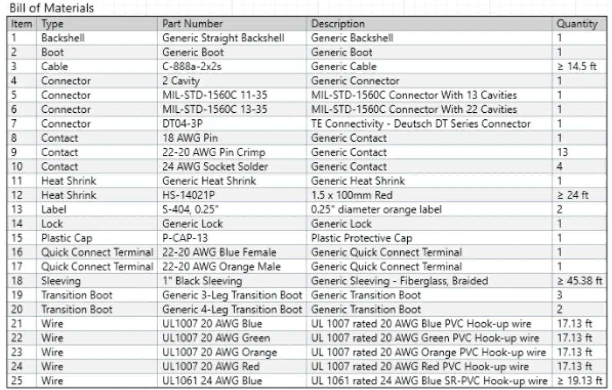
This project documents a repeatable methodology for designing automotive wiring harnesses inside 3DEXPERIENCE (CATIA V6). The output is not a single harness but a recipe: given a schematic, a connection table and a vehicle CAD model, follow these steps in this order and the result is a manufacturable harness with a complete drawing pack and bill of materials. The methodology covers the full chain — from how the electrical inputs are organised, through how cables are packaged and routed in 3D, all the way to the manufacturing deliverables — so that the next engineer who picks up the tool produces work that integrates cleanly with the rest of the vehicle programme rather than having to reinvent conventions every time. As a worked example, the same methodology is applied end-to-end to a Battery Management System harness, so that the abstract steps land on a concrete deliverable: components defined, electrical tree built, packaged in the chassis, bundles routed, and manufacturing drawings generated.
How it’s structured
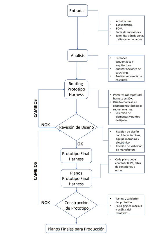
The work is organised around the three stages of harness design that 3DEXPERIENCE expects you to keep separate: a logical stage where the schematic, connection table and BOM live; a physical stage where each component, connector and cable has a defined geometry; and a routing stage where bundles are laid out in the vehicle. The logical stage is built from the architecture block diagram supplied by the electronics or hardware team, the schematic that fixes pinouts and signal names, and the connection table that calls out wire gauge, colour, and any harness-specific notes. Securing and protection are treated as their own subsystem because the choice of material drives how the harness behaves over the vehicle’s life, and because clip type and spacing are what determine whether the harness survives vibration. The methodology also calls out clearance from sharp edges and heat sources, minimum bending radius, and heat-shrink placement as design rules that must be checked at the routing stage, not after manufacturing drawings are released.

flowchart TD
A[Architecture Block Diagram] --> B[Schematic + Pinouts]
B --> C[Connection Table]
C --> D[Logical Stage in 3DEXPERIENCE]
D --> E[Physical Stage:<br/>Components, Connectors, Cables]
E --> F[Packaging in Vehicle CAD]
F --> G[Routing Stage:<br/>Bundles, Clearance, Bend Radius]
G --> H[Securing & Protection<br/>Material + Clip Spacing]
H --> I[Manufacturing Drawings + BOM]
How it works
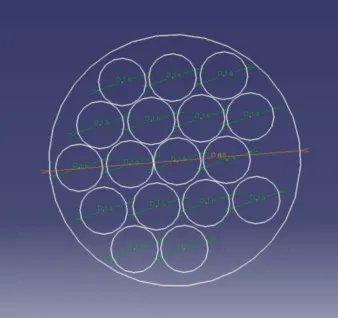
In practice the workflow starts from the schematic and the connection table and turns them into a structured tree of components inside 3DEXPERIENCE. Each component is given its electrical characteristics — pinout, signal name, gauge, outer diameter — so that the software can later compute bundle sizes and validate compatibility. Routing is then executed against the vehicle CAD: cables follow the packaged paths, avoiding sharp edges, moving parts and heat sources, while clips and clamps are placed at the recommended spacing. Bundle diameters drive the routing tolerance, and slack is added explicitly where the chassis flexes or where service access is required.
Securing materials. Braid sleeving holds bundles together, provides thermal insulation and reinforces the existing electrical insulation. Five materials cover the practical envelope of automotive and aerospace harness work, and the methodology asks the engineer to pick the right one against the operating environment rather than defaulting to whichever is cheapest:
Nylon (PA66): flexible and lightweight, with respectable tensile strength against the cable bundle masses typical of automotive harnesses, which makes it the default for low-stress installations. It tolerates moderate vibration but loses stability at sustained high temperatures and degrades under prolonged UV or chemical exposure, so it is best kept inside the cabin or in protected engine-bay locations. Typical use is for cable ties, simple sleeving on signal harnesses, and any run where the dominant requirement is “cheap, light, easy to terminate”.
Polyester (PET fabric tape): offers excellent abrasion resistance and a noticeably higher continuous-temperature rating than nylon, with good tensile strength once wrapped under tension and strong vibration tolerance. The woven structure conforms tightly to bundles of irregular cross-section without leaving gaps that would let the cables chafe inside the sleeve. Typical use is for engine-bay routing, alternator and starter loom protection, and any harness segment that has to survive contact with sharp edges over the vehicle’s life.
PET: Polyethylene Terephthalate as a sleeving material delivers extreme resistance to fluids, oils, brake fluid and most automotive chemicals, with good tensile strength and a temperature range that comfortably exceeds nylon. It tolerates the high-frequency, low-amplitude vibration typical of road-load spectra without losing dimensional stability. Typical use is for harness segments routed near the gearbox, fuel system, or anywhere the cables can be exposed to harsh substances during normal operation or during service.
PPS: Polyphenylene Sulfide combines very high resistance to acids, fuels and elevated temperatures with strong tensile strength even after long thermal soak, which is why it is the default choice when the operating envelope pushes past where polyester or PET can survive. The material’s vibration tolerance is excellent and it does not embrittle at the temperatures that would degrade nylon. Typical use is in aerospace, telecommunications and motorsport applications where the cable bundle has to survive both chemical attack and thermal cycling without measurable degradation across the design life.
Nomex: an aramid fibre prized for its expandability, very high heat and flame resistance, and strong protection against moisture, chemicals and abrasion. It has excellent tensile strength and outstanding vibration tolerance, with a continuous-use temperature that puts it in a different class from the polyester family, though it is more expensive and less flexible than nylon. Typical use is for fire-zone runs, motorsport powertrain looms, and any harness segment where flame propagation along the bundle is part of the failure mode being designed out.
Aspects to avoid in harness design. The technical-considerations section of the methodology catalogues the conditions that the engineer is expected to design against, not discover on the prototype. The four categories that the methodology enumerates are:
- Interference with sharp or moving parts — avoid routes that bring the harness into contact with edges or articulating components, and add protective coverings or alternative routing if the contact cannot be avoided.
- Crushing and trapping risks — design routes so that the harness is not pinched by adjacent vehicle components in normal operation or trapped during maintenance access; this means leaving service slack at the right locations rather than just adding sleeving.
- Heat sources — keep the harness clear of exhaust manifolds, turbochargers and other thermal sources that would degrade the insulation and cause electrical failures over time.
- Electrical interference — position harnesses so that they do not run parallel to high-noise sources such as spark-plug leads, ignition coils or unshielded high-power cables, and add shielded segments where parallel routing is unavoidable.
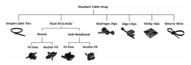
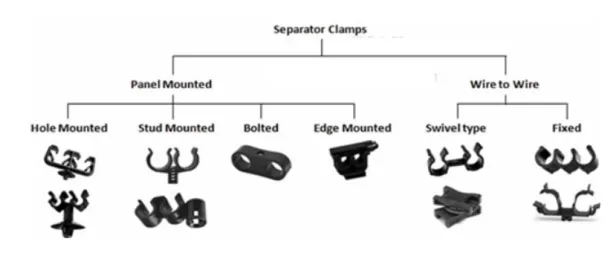
Clip and clamp guidance. Securing the harness inside its envelope is a separate decision tree from the sleeving choice. The methodology calls out a small catalogue of clip types — P-clips for through-bolt mounts on tubular structure, plastic edge clips for sheet-metal flanges, and snap-fit clips for blind hole locations where the technician cannot access the back side — and asks the engineer to size each clip against the bundle diameter rather than picking a single part across the whole harness. Spacing recommendations split by orientation: horizontal runs get clips at roughly every 200–300 mm depending on bundle weight, while vertical runs are tightened up because gravity adds a downward sag-and-pull load that is absent in horizontal segments. The same logic drives clearance: minimum distances from sharp edges, moving parts and heat sources are checked at routing time, and the methodology requires the engineer to call out where additional protective coverings replace the clearance budget if the chassis geometry forces a closer pass.
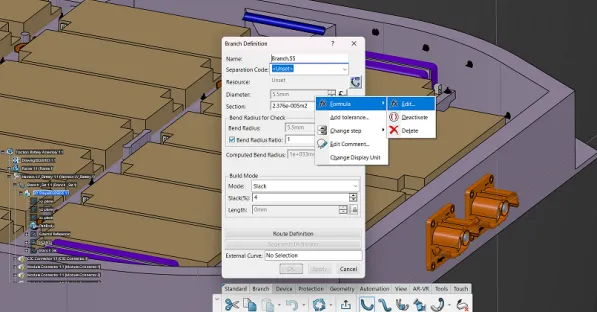
Bending radius. Cable fatigue and insulation cracking are dominated by the minimum bending radius the cable sees over its life, especially in segments where the chassis flexes or where the harness crosses an articulating joint. The methodology specifies a minimum bend radius proportional to the cable outer diameter, derives it from the cable manufacturer’s published value, and validates each routed segment against that figure inside 3DEXPERIENCE before drawings are released.
Heat shrink application tips. Heat-shrink tubing is used to add insulation, mechanical protection and strain relief at junctions, splices and connector backshells. The methodology calls out three placement rules that catch most of the field failures: shrink lengths are sized so that they overlap the protected segment by at least the tube’s recovered diameter at each end; the shrink is positioned so that it never bridges a connector latch or any feature the technician needs to actuate during assembly or service; and dual-wall, adhesive-lined shrink is preferred wherever the joint will see moisture, vibration or thermal cycling, because the adhesive seals the cable jacket and prevents wicking that bare-shrink installations cannot stop.
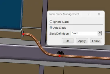
Cable assemblies, service accessibility, slack and flexibility. Once the bundles are routed and the materials and clips are chosen, the methodology asks for an explicit pass over how the harness will be serviced. Cable assemblies are constructed so that connector pairs land in accessible locations — never inside a closed cavity that requires partial vehicle disassembly to reach. Service accessibility means leaving enough room around each connector for a tool, a hand, and a flashlight, and means routing the harness so that the technician can disconnect a faulty branch without disturbing adjacent harnesses. Slack and flexibility are provided wherever the chassis flexes relative to the cable mount or wherever the harness has to move during normal operation, with a documented slack length per segment so that the manufacturing floor knows how much extra cable to cut. Done up front, these three checks turn the harness from a static drawing into something the service team can live with for the life of the vehicle.
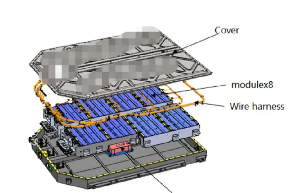
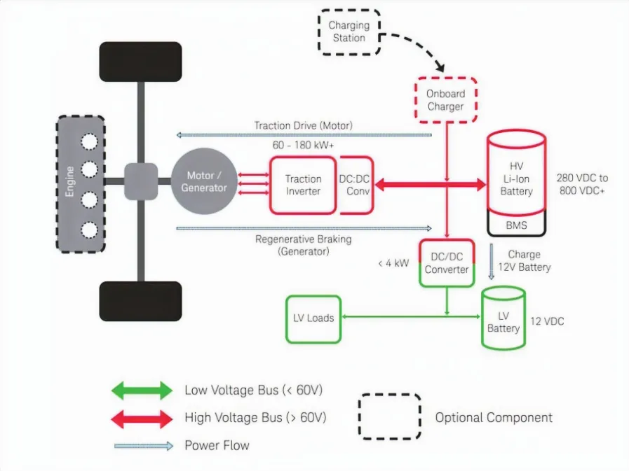
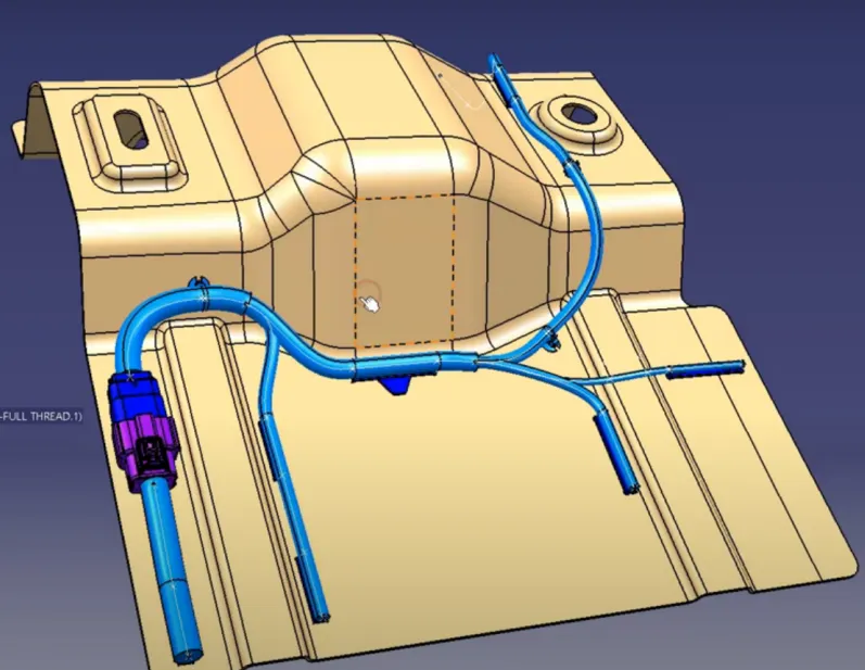
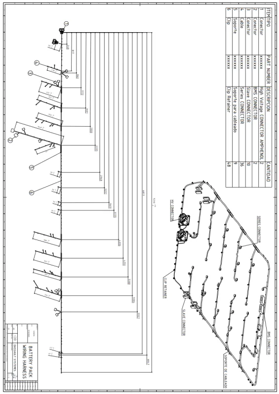
Worked example: BMS harness in 3DX. With the design rules captured, the methodology was applied end-to-end to a Battery Management System harness on an electric vehicle. The first step was to set up the BMS harness inputs against the architectural overview of the vehicle — module layout, interconnection points, sensor and connector specifications.
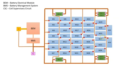
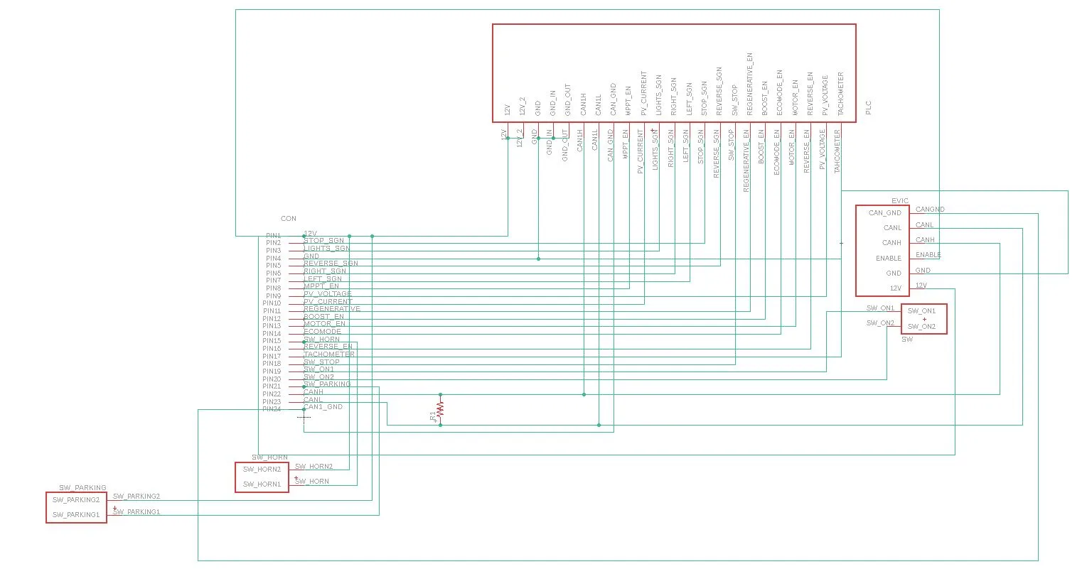
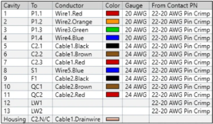
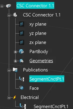
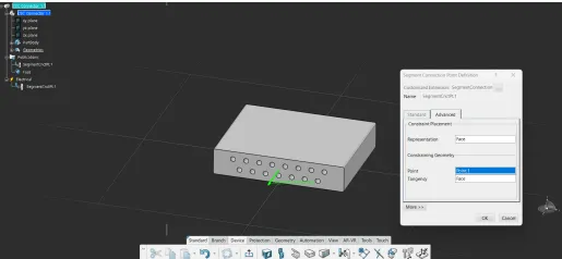
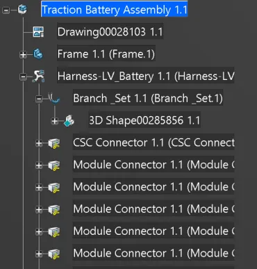
The next step was to define the electrical characteristics of every physical component in 3DEXPERIENCE so that the software could later validate bundle sizes and pinout compatibility — a one-time setup cost that pays off across every subsequent design iteration. From those component definitions, the harness tree was built up in 3DX, hierarchically organising the BMS, the cell modules and the auxiliary connections so that the layout step had a clean structure to start from.
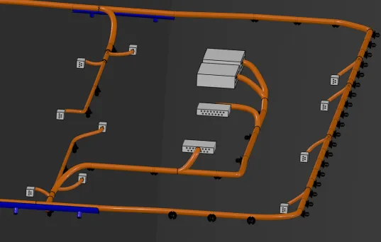
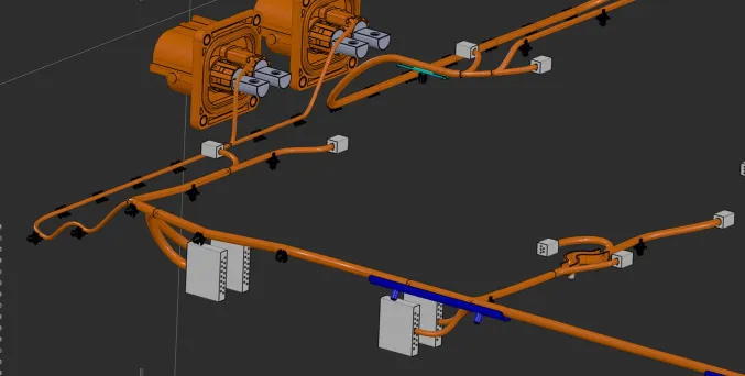
Component placement inside the chassis followed, prioritising efficient routing paths and accessibility for service. Looms and bundles were then defined, with bundle diameters computed from the cable outer diameters that came in via the schematic.
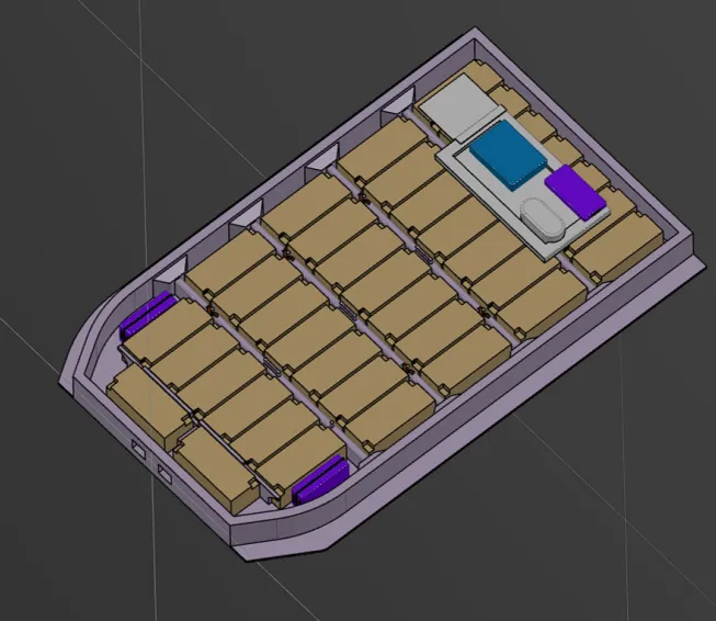
A Jaguar reference build was used to cross-check the methodology — a known-good production harness on a comparable vehicle gave a yardstick for whether the BMS harness was over- or under-engineered relative to industry practice.
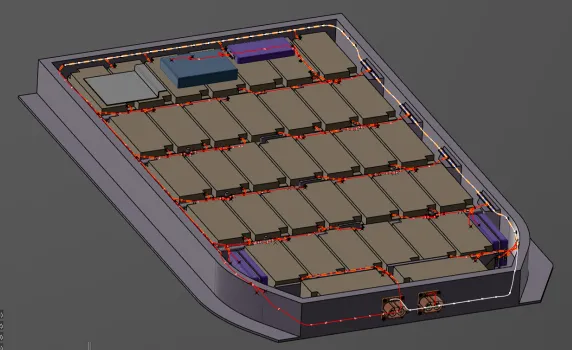
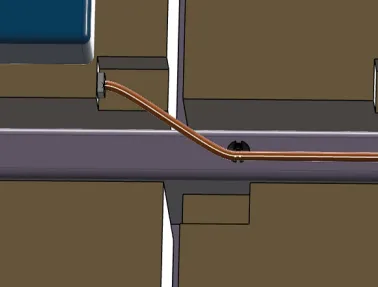
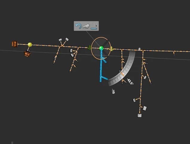
The routing pass laid out the physical paths through the vehicle, respecting the design rules from earlier in the methodology — clearance, bending radius, sharp-edge avoidance — and the slack-management pass added the extra cable required at each flex zone.
The harness design then converged on its result, evaluated for functionality, safety and manufacturability across multiple result iterations.
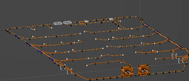
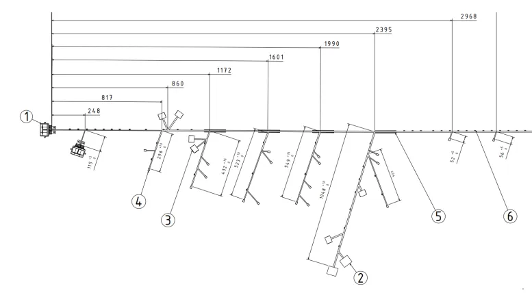
Drawings. Manufacturing preparations are the last step before handing off to the harness shop. The 3DX harness model is converted into a flattened representation that the manufacturing floor can read directly, and detailed drawings are generated that capture every cable length, connector orientation, sleeving call-out and clip location. The drawing-generation discipline is what determines whether the harness shop builds what was modelled or makes a slightly different harness that integrates badly with the vehicle — this is the stage where every preceding decision either pays off or forces a rework cycle.
What I learned
The biggest takeaway was how much harness quality depends on the order of decisions, not the cleverness of any single one. If you fix component placement before you understand routing, you end up forcing cables into expensive paths; if you delay protection choices, you discover at the prototype stage that the chosen sleeving cannot survive the engine bay. Documenting the sequence as a logical diagram — schematic, packaging, routing, securing, drawings — turned out to be the most useful artefact of the project, because it lets the next engineer make the same calls in the same order. I also learned to treat the rules around clearance, bending radius and heat shrink as first-class design constraints rather than annotations on a drawing: encoding them up front in 3DEXPERIENCE prevents the kind of late surprises that derail a build schedule. The securing-material catalogue ended up being the single highest-leverage piece of the methodology — picking nylon, polyester, PET, PPS or Nomex against the operating environment, instead of defaulting to whatever the previous build used, is what turned the harness from an engineering hazard into a serviceable component for the life of the vehicle.