Human-Powered Vehicle.
Tricycle-style human-powered vehicle with a CAD-modelled, FEA-validated 1045-steel chassis and a documented build process.
- Year
- 2020
- Role
- Mechanical Designer
- Domain
- Mechanical
What it does
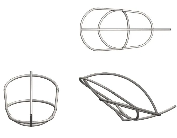
This project designs and builds a tricycle-style human-powered vehicle from scratch — chassis geometry, structural simulation, fabrication and assembly. The aim is to produce a vehicle that one rider can pedal comfortably, that handles predictably, and that is structurally sound under representative loads. The project also has explicit pedagogical objectives — understanding through construction how different mechanisms work, applying knowledge from previous Solid Mechanics and Conceptual Design courses, and gaining hands-on experience with materials and workshop tools — so each step is documented so the design choices can be inspected and reproduced. The deliverable is the rolling chassis: a SolidWorks model of the geometry, an FEA campaign that confirms the design will not yield or tip under the expected loads, and a build-process record showing the path from sketches to physical vehicle. The CAD model serves as a blueprint for the physical build: it captures the structure, the dimensions and the design features that emerged from the sketching and planning phases, and it is the artefact every later stage refers back to when a question comes up on the workshop floor.
How it’s structured
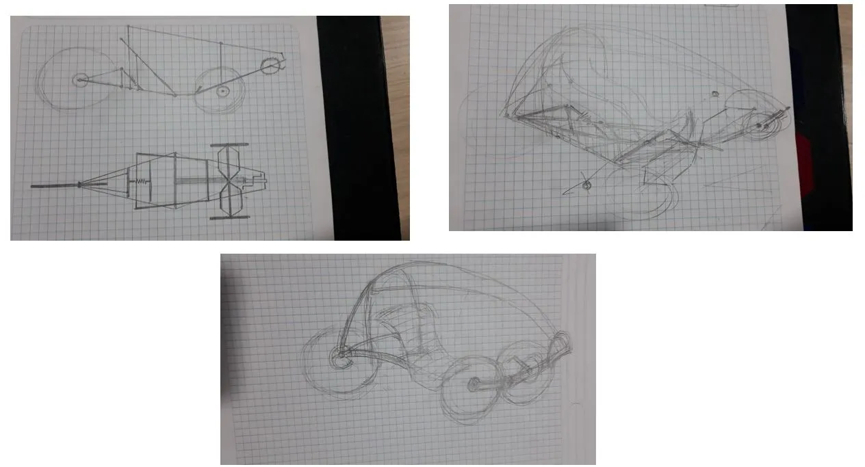
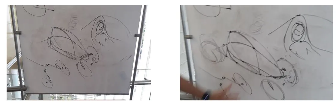
The work is organised in three stages: chassis design, structural simulation, and build. The chassis design stage starts with hand sketches that fix the seating position, wheel geometry, and rider ergonomics, then moves into SolidWorks for a full 3D model where each tube, joint and mounting point is defined. The state-of-the-art review showed that most human-powered vehicle frames are based on a single structural bar that runs the length of the tricycle — usually tubular, sometimes square — so the team chose to base the design on a central tube from which the rest of the chassis extends.
The simulation stage takes that geometry and runs a structural analysis with mesh refinement, looking for displacement, stress, yield-limit margins and a safety factor against tipping. The build stage turns the validated CAD into the physical vehicle: cutting tubes to the lengths the model specifies, jigging the geometry so that welding does not pull the chassis out of alignment, welding the joints, and assembling the rolling chassis. Treating the project as three discrete stages — sketch → simulate → build — keeps each step honest, because every transition forces the previous one to commit to a clear set of dimensions or load assumptions, and a problem found at one stage is cheap to fix before the next begins.
How it works
After the geometry is fixed in CAD, the chassis is simulated as a portal frame structure to obtain precise results and to define the material and gauge of the tubing that would make up the tricycle. Two loads are applied to the vehicle in the simulation: the first, drawn with a red arrow at the rider position, represents a 90 kg person — equivalent to 882 N of vertical load — and the second, a 1,962 N load equivalent to a 200 kg mass at the top of the chassis, is added to analyse the chassis’s resistance to a rollover and is drawn with a yellow arrow. The remaining arrow indicates that the simulation runs under gravity at 9.81 m/s². The material parameterised for the simulation is 1045 steel, chosen for its yield strength and machinability against the gauge of tubing the design called for.
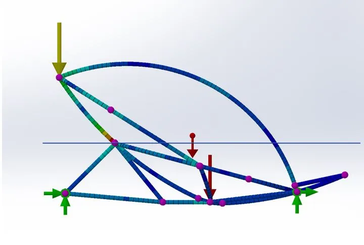
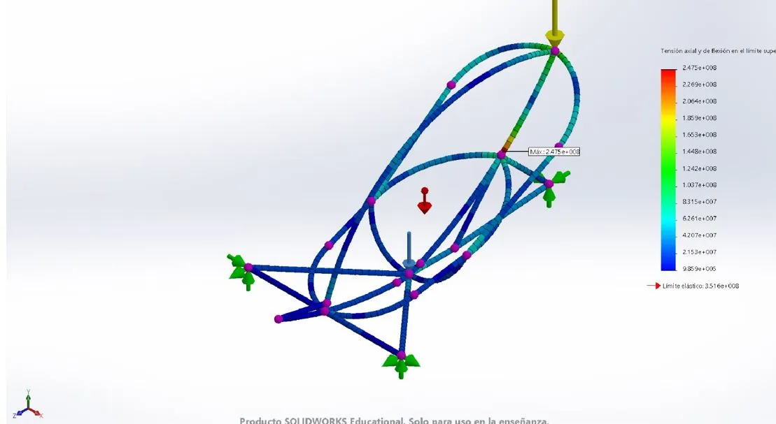
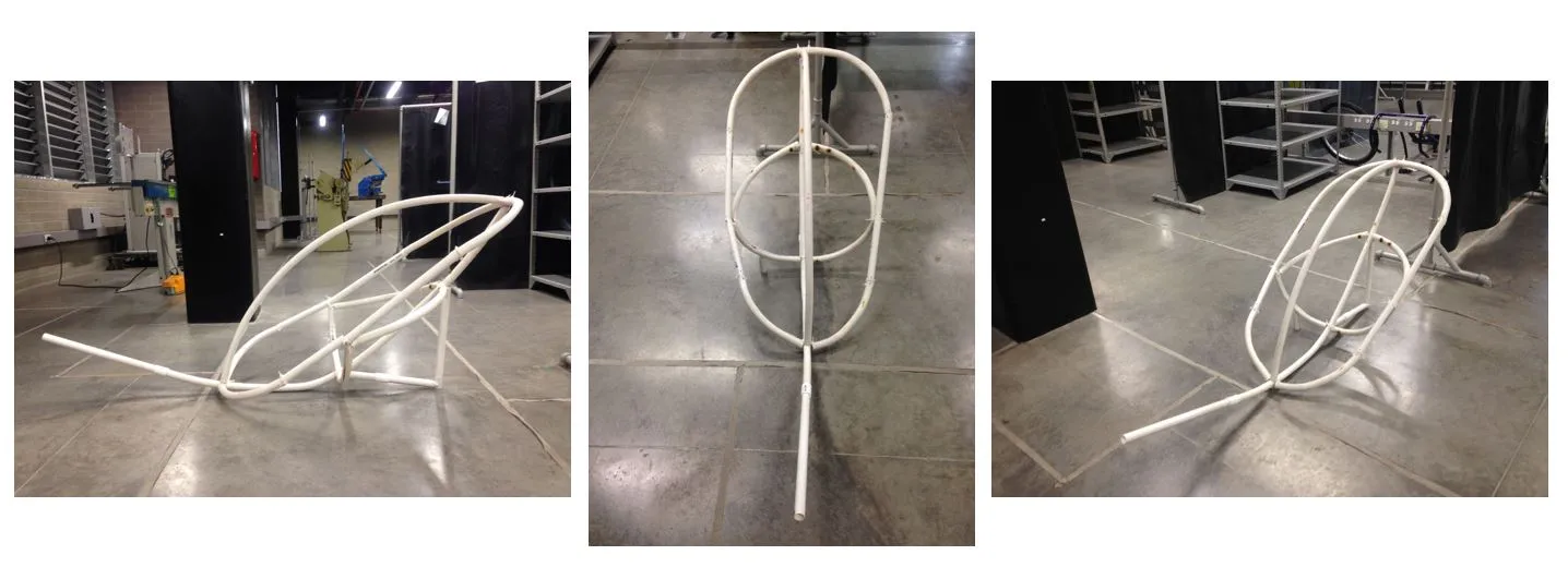
The simulation results are then analysed to ensure that there are no large displacements or stresses exceeding the yield limit of the 1045 steel. Two findings dominate the analysis: the displacements under load stay below the threshold the design called for, with no part of the geometry exceeding the yield limit of the chosen steel; and the chassis shows a safety factor of 1.4 against overturning, meaning the geometry can absorb a 40 % overload before it begins to permanently deform. With that confidence in the structural envelope, a soft model is made from PVC piping to validate the spaces inside the tricycle and to interface with the pilot — a proactive measure to catch ergonomics issues before any 1045-steel tube is cut.
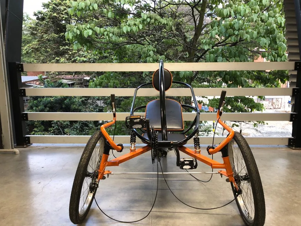
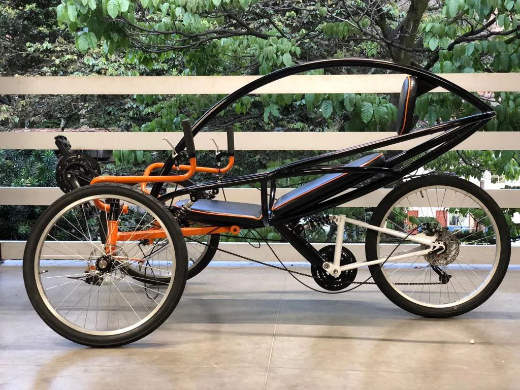
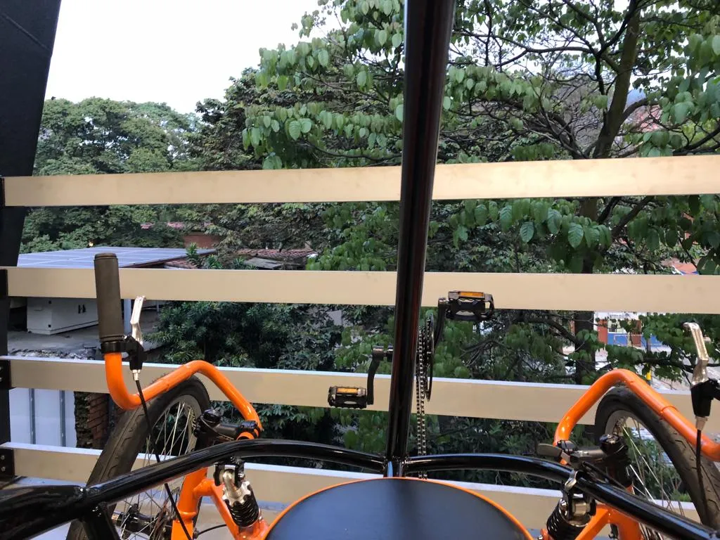
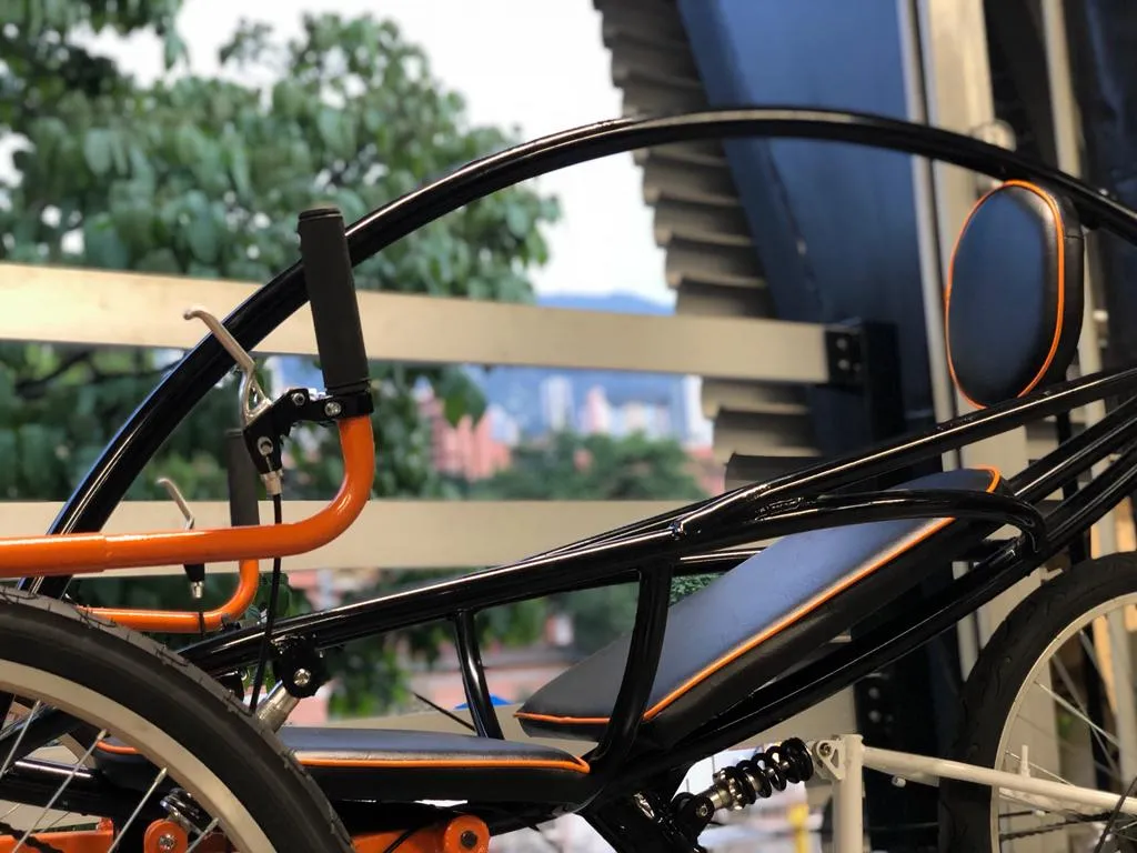
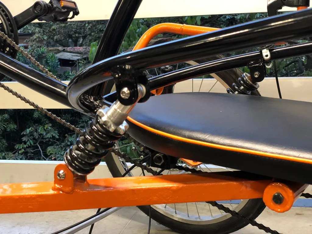
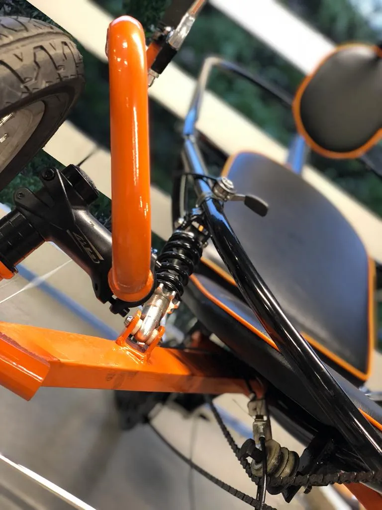
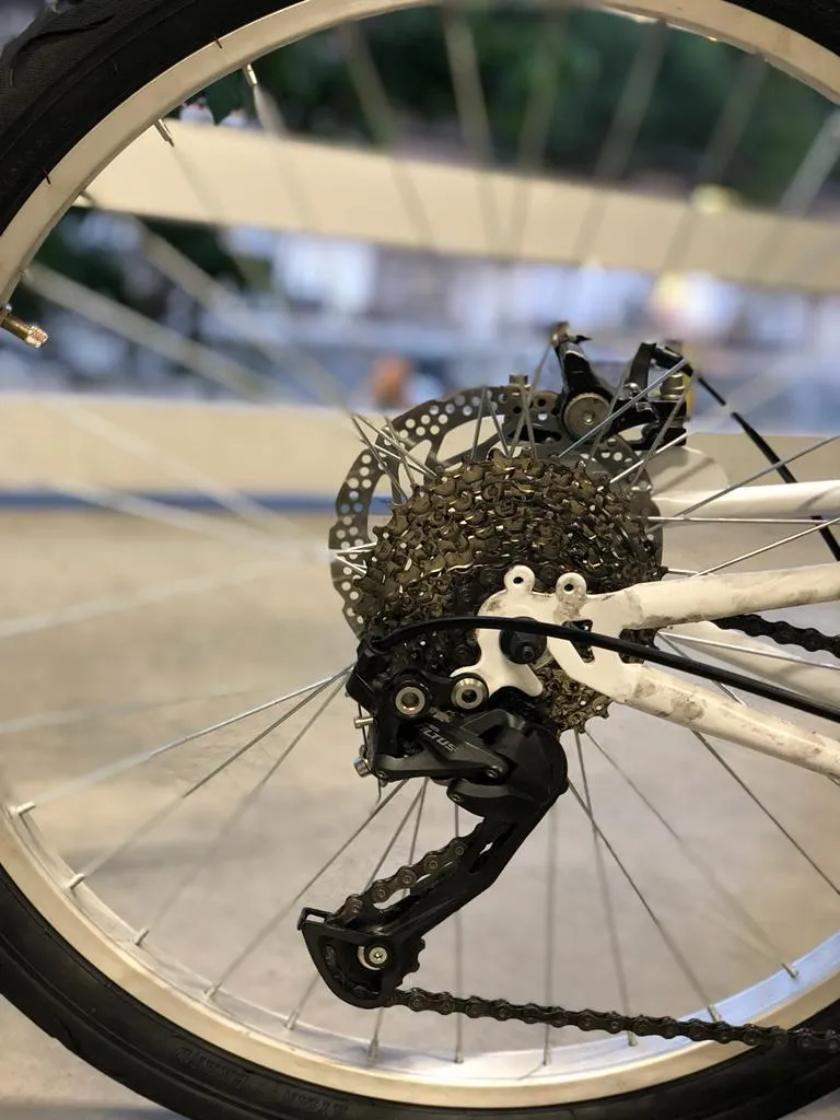
After verifying the distances and confirming there are no ergonomics issues, the manufacturing stage proceeds and many commercial bicycle parts — transmission, pedals, brakes, suspension — are integrated so that the final design stays both practical and serviceable, since standard parts are available and easy to maintain.

What I learned
The biggest takeaway was the value of FEA as an honest reality check before any tube was cut. Discovering, on screen, that the chassis would tip at a 40 % overload and not before, gave the team the confidence to commit to the geometry and let the build stage move quickly without revisiting design decisions. I also learned how much CAD ergonomics matter for a vehicle that interacts with a human body: small choices about seating position, pedal location and handlebar height directly shape how the rider applies power and how the chassis is loaded, and pinning those choices early avoided a lot of late-stage rework. Choosing 1045 steel rather than a higher-grade alloy was the right call once the load cases were sized — 882 N rider and 1,962 N rollover — because the safety factor of 1.4 left room for assembly tolerances and weld-influenced zones without forcing the team into more expensive material. Finally, treating the build itself as a documented engineering activity — not as the casual end of the project — turned out to be one of the more useful habits: photographing every stage made the post-mortem on welds and fitment far easier than it would have been from the finished vehicle alone.
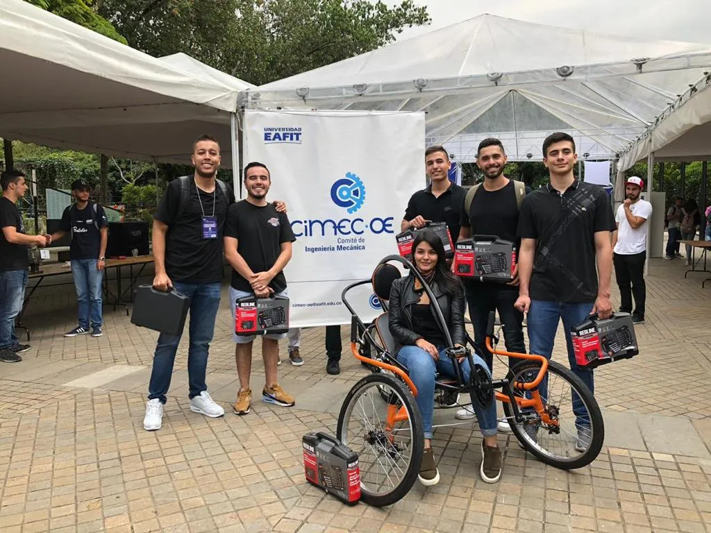
This tricycle was a team effort with Pablo López, Martín Llano, Thomas Parra, Felipe Obando and Sara Restrepo, who shared the sketch, simulation and build stages and turned the central-tube concept into a vehicle that actually rolled.