Battery System — KRATOS Solar Car I.
Design and build of the 26S50P main pack and 4S1P auxiliary pack for KRATOS Solar Car I, including FEA-validated case for the iLumen European Solar Challenge 2018.
- Year
- 2018
- Role
- Battery Engineer
- Domain
- Energy

What it does
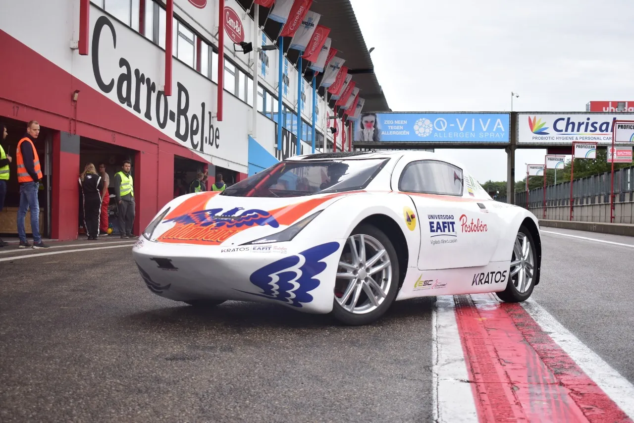
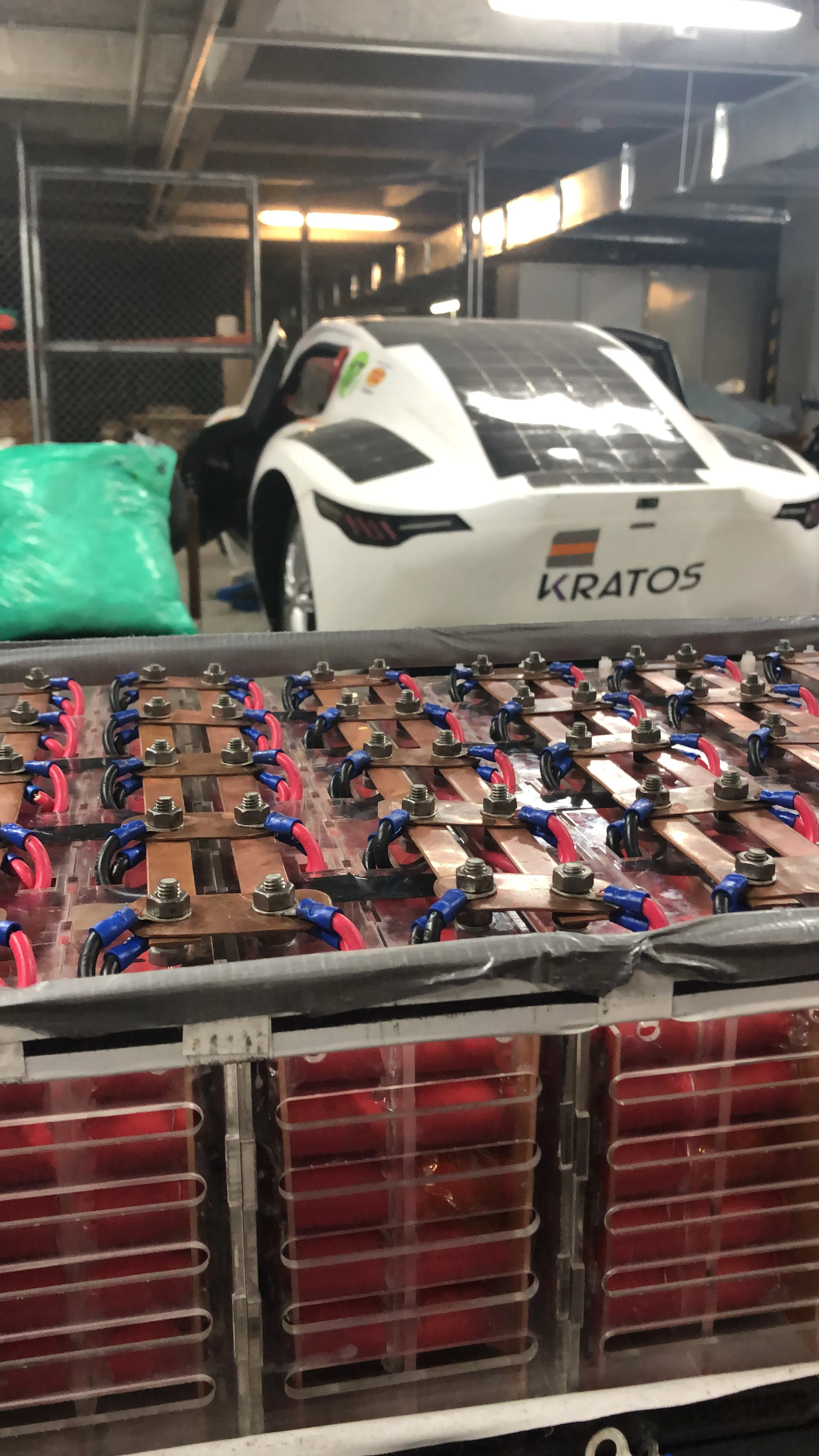
This project is the original main and auxiliary battery pack for KRATOS Solar Car I, the EAFIT University entry to the iLumen European Solar Challenge 2018 at the Zolder circuit in Belgium. The system stores all of the energy used to drive the vehicle through the cruiser-class race, supplies the 12 V auxiliary loads, and presents itself to the rest of the car through an Orion BMS so that charging, discharging and protection can be supervised continuously. The deliverable is the full pack: cell selection, electrical architecture, mechanical case, BMS integration, transport-compliant submodule packaging, and the assembly that was actually installed in the vehicle and raced. The pack ultimately drove a vehicle that took the fastest lap of the competition, was judged the second most innovative vehicle, and finished as the third fastest car in its class — and the design choices documented here are the ones that made that result possible on a tight student-team budget.
How it’s structured
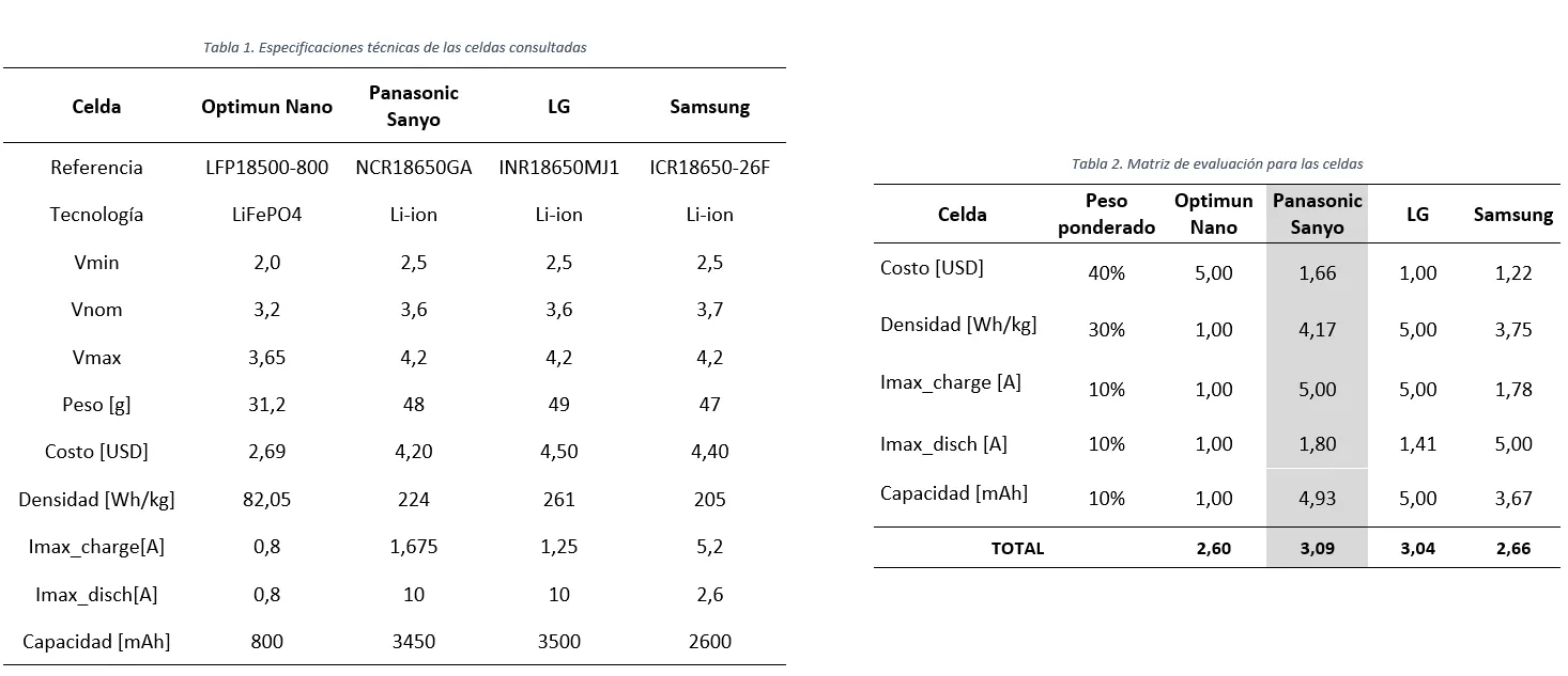
Before any cells were ordered, the team ran a selection study against five criteria — cost per unit, gravimetric density, maximum discharge current, maximum charge current, and energy capacity — and used the cruiser-class regulation that caps the total cell mass at 63 kg to bound the upper limit on cell count. The exercise filtered the available 18650-format chemistries and converged on the Panasonic/Sanyo NCR18650GA, a 3.6 V 3,450 mAh cell whose combination of energy density and continuous discharge rating beat the alternatives once each criterion was weighted. The same matrix is what justified the choice to the rest of the car team and to the race scrutineers, because the cell choice fixed every downstream parameter — pack voltage, parallel count, submodule size, case volume, BMS sense-line layout — and any change at the cell level would have rippled through the whole architecture.
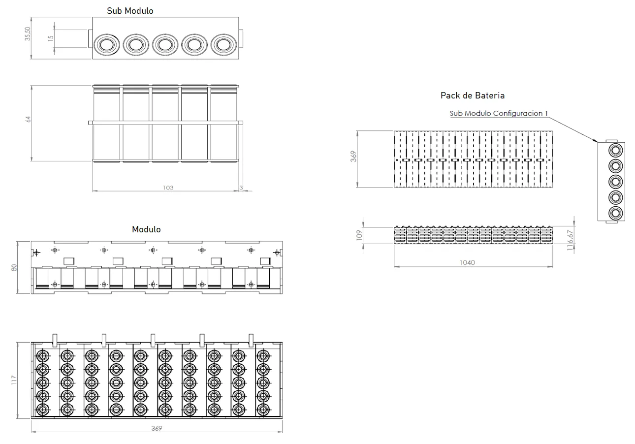
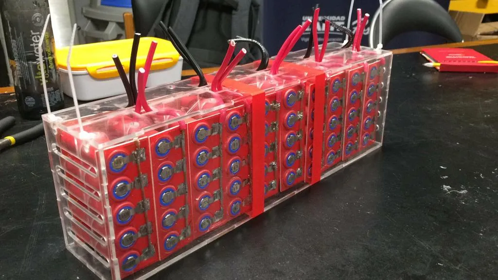
The result was 1,304 cells split between a 96 V main pack and a 12 V auxiliary pack: 1,300 cells configured as 26S50P for the main, plus a 4S1P auxiliary. The main pack voltage was set at 96 V because the available motor catalogue clustered around that value, which let the rest of the powertrain reuse off-the-shelf controllers and chargers without custom rewinds. To stay inside the 100 Wh limit per package required for lithium-battery air shipment, the main pack was further broken down into submodules of 5 parallel cells, which then aggregate into 26 modules and finally a single pack. Around the cells, the architecture is wrapped in a 1020-steel case, the Orion BMS, and the high-voltage interconnects to the rest of the powertrain.
How it works
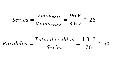
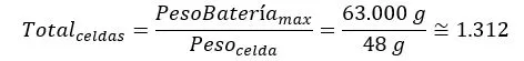
Cell selection drove every other decision. The maximum cell count is bounded by the cruiser-class mass cap, and the team derived it from a closed-form expression that divides the regulated cap by the per-cell mass — that derivation is captured in equation 1, rehosted below, which yields 1,312 cells as the upper bound and which is what the 1,304-cell final architecture sits inside.
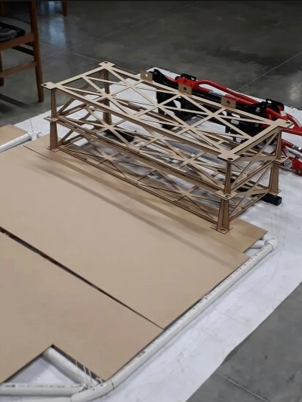
Once the cell was chosen, the 96 V nominal target — picked because the available motor catalogue clustered around that voltage — fixed the series count, and the 63 kg mass cap fixed the parallel count. The submodule, module and pack hierarchy was then sized against the available volume given by the body and structure subsystems, with multiple iterations needed to make the architecture lighter and to fit the chassis. The case was modelled in SolidWorks and validated with a structural FEA campaign: load conditions came from the static weight of the pack plus the equivalent loads under acceleration, deceleration and cornering, and the boundary conditions captured the way the case is bolted into the chassis. The mesh was then refined across ten simulations, each one decreasing the maximum element size, until convergence was reached on stress, displacement and the modulus of elasticity supplied by the steel vendor.
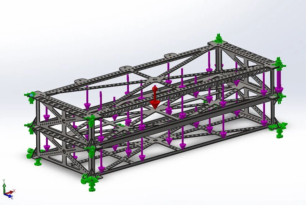
After convergence, the team ran an H-method refinement with 5 adaptation cycles and a stopping criterion of 99 % accuracy, against the Von Mises failure criterion, and obtained a safety factor of 1.5 — which is the number that ultimately authorised the build. With the simulation campaign closed, a soft model was manufactured to validate fitment inside the body and to flush out any conflicts that would have shown up only when removing the battery from the vehicle for servicing. Only after that did the team commit to the final case in 1020 steel.
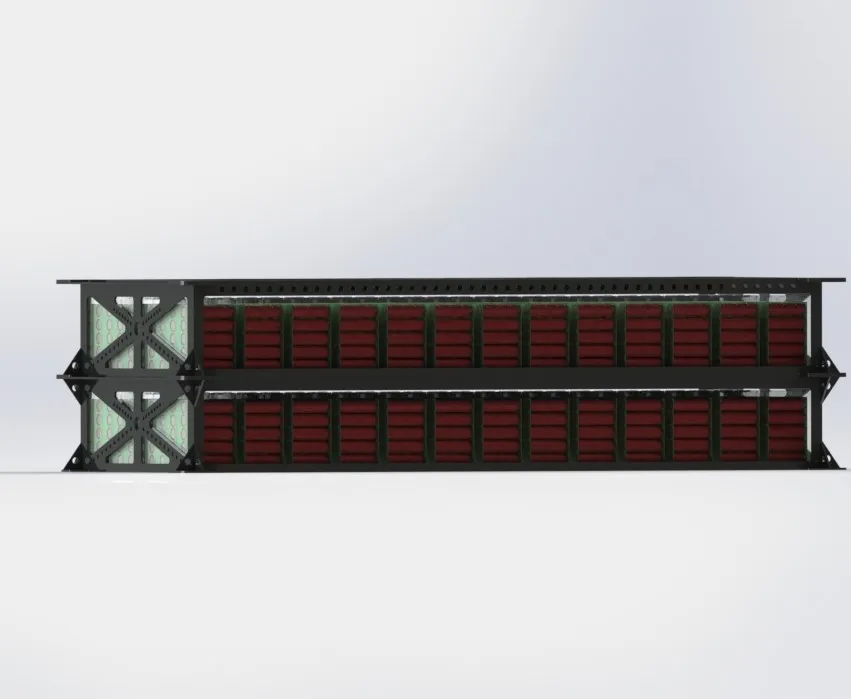
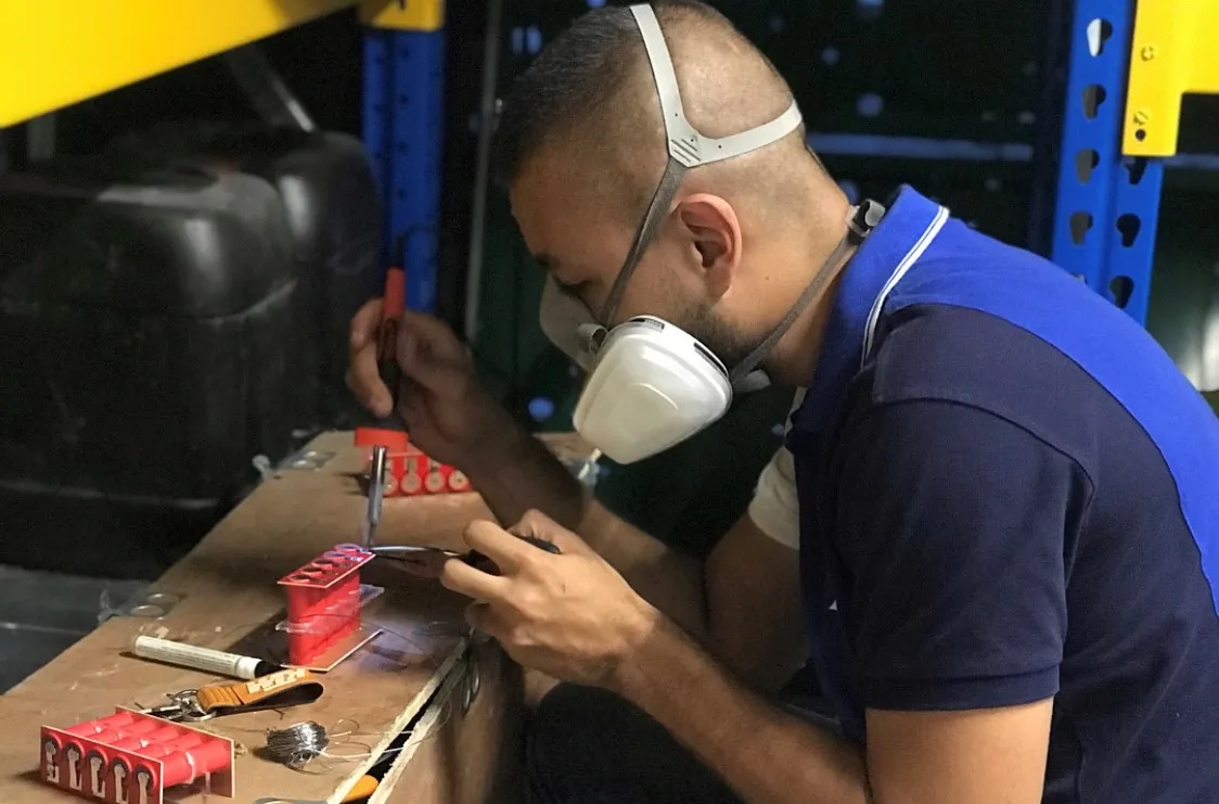
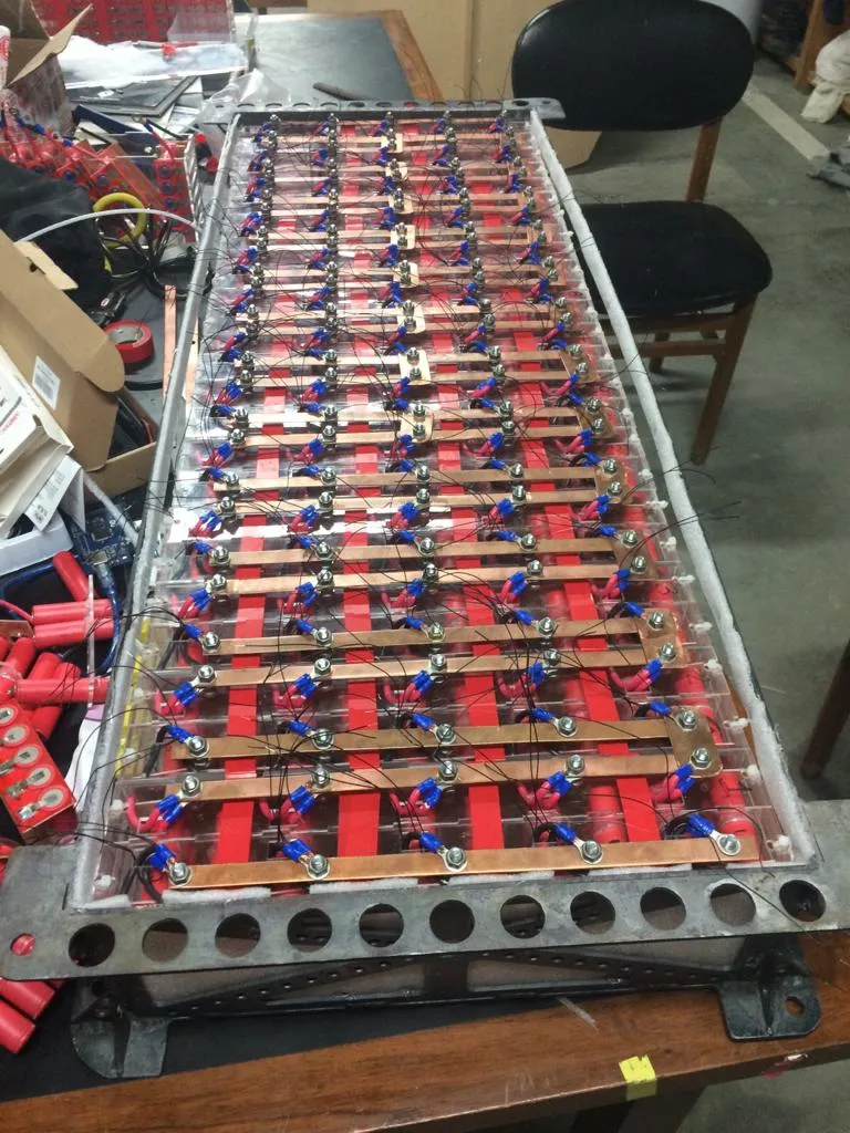
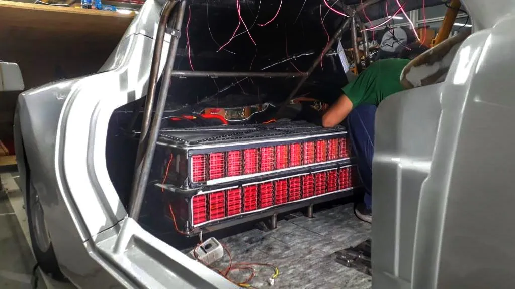
Manufacturing followed the architecture: submodules of 5 parallel cells were built first, 26 of those were combined into modules, the modules were interconnected, the Orion BMS was wired to each, and finally the assembled pack was installed in the vehicle and connected to the high-voltage unit. The submodule-first sequence kept the assembly inside a manageable bench footprint and made each step independently inspectable.
What I learned
The biggest takeaway was how much battery design is dominated by external constraints. The cruiser-class mass cap, the 100 Wh per-package air-shipment limit, and the regulated motor voltages all sat upstream of the engineering decisions, and respecting them up front made the cell selection straightforward and the architecture choices defensible. I also learned that battery case design rewards a converging FEA campaign rather than a single hero simulation: ten mesh-convergence simulations followed by an H-method refinement of 5 cycles to a 99 % accuracy stop, all checked against Von Mises and held to a safety factor of 1.5, were what convinced us the case was light enough to ship and strong enough to race. Finally, breaking the pack into submodules turned out to be a structural decision as much as a logistical one — being forced to design at the 5-cell granularity made manufacturing, transport and field service all simpler, and let the team deliver a vehicle that took the fastest lap of the competition, the second most innovative vehicle, and the third fastest in the chicane test for an overall fourth-place finish in cruiser class.
This project would not have happened without the rest of the KRATOS electronics subsystem — Leonardo Santa, Juan Camilo Ramírez and Thomas Parra — who shared the design, build and trackside debugging that turned the architecture above into a battery that actually raced.