SAE J1772 Charging System — KRATOS Solar Car II.
SAE J1772 compliant on-board charging system for KRATOS Solar Car II, including control electronics, finite state machine and FEA-validated Aluminum 7075-T6 mounting brackets.
- Year
- 2022
- Role
- Electrical / Electronic Lead
- Domain
- Electrical

What it does
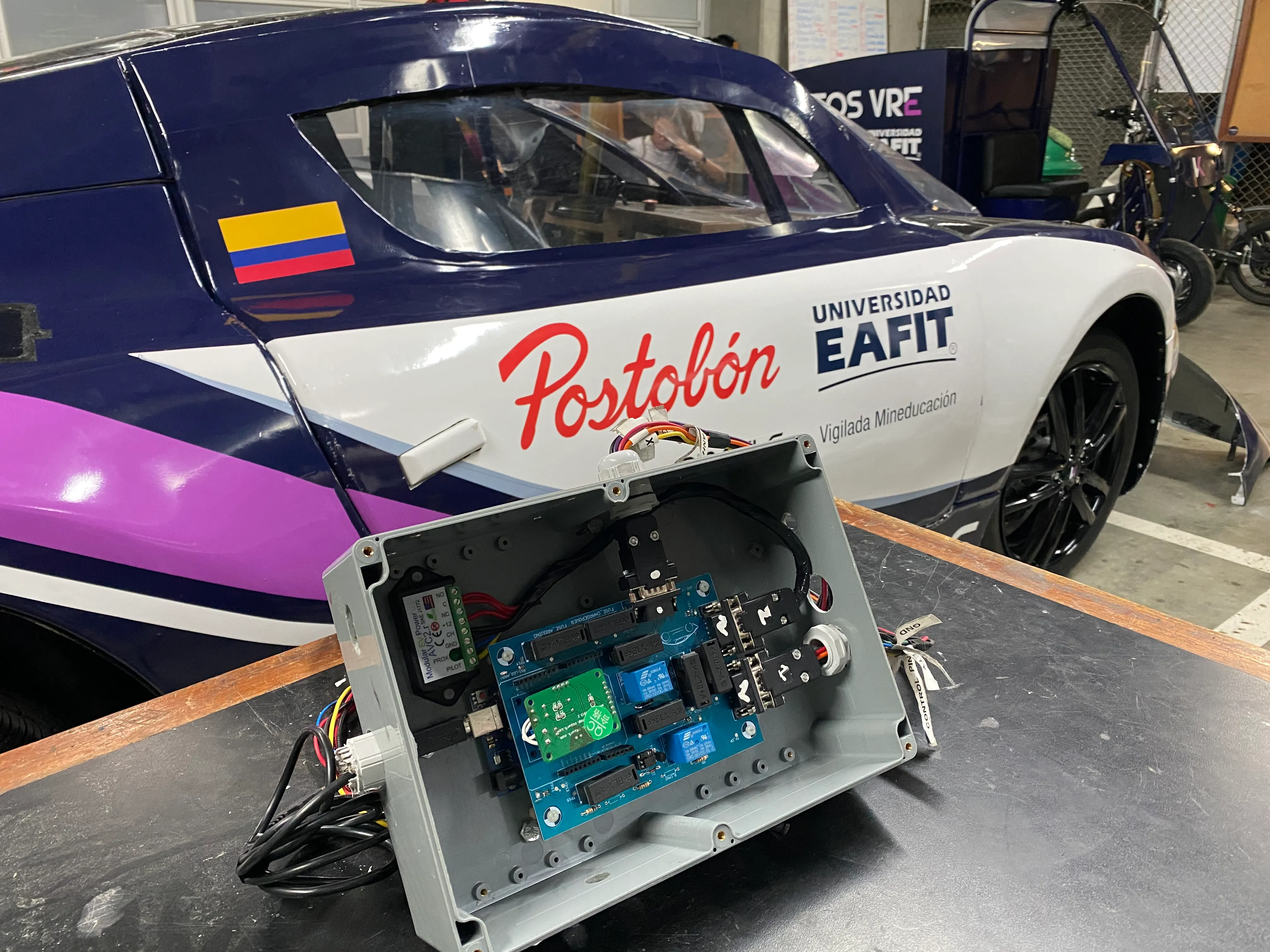
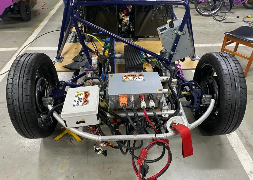
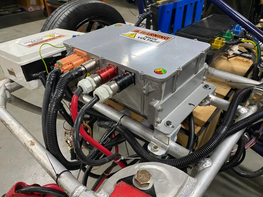
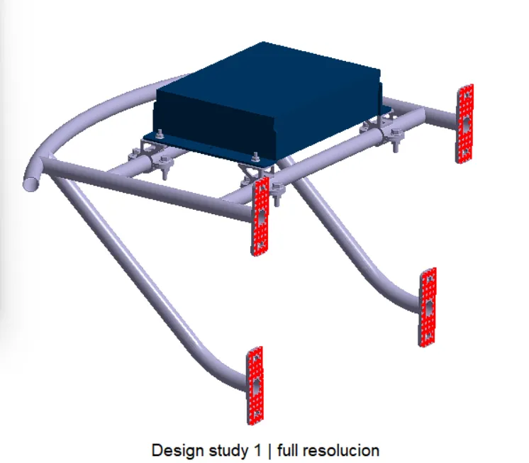
This project delivers a complete on-board charging system for KRATOS Solar Car II, the EAFIT University team that competed in the iLumen European Solar Challenge 2022. The system lets the car plug into any SAE J1772 compatible station, negotiate the available current with the charging equipment, and feed energy safely into the high voltage battery. Beyond the electronics, the project also covers the mechanical brackets that secure the rectifier inside the cabin, since the unit weighs 12.7 kg and shares the cockpit with the driver — meaning the design has to survive a frontal impact without becoming a projectile. The deliverable is the working charger installed in the vehicle: PCB, control firmware, brackets, and the validation evidence that the assembly is safe to race. The whole project was scoped to be designed, built and integrated into the car within an 18-week window in parallel with the rest of the powertrain development, so the structure of the project — running the electronics and mechanical workstreams together — is as deliberate as any of the technical choices, with each workstream allocated roughly half of those 18 weeks before the integration milestones at the end of the schedule.
How it’s structured
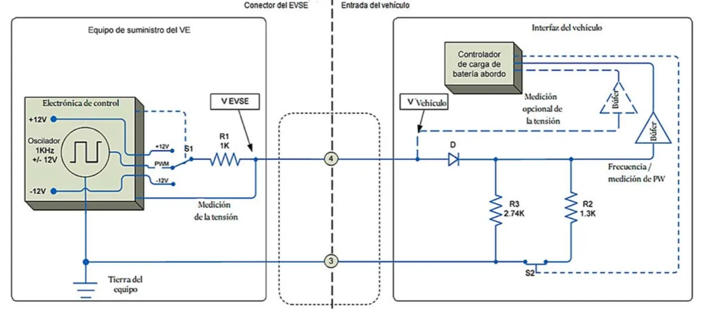
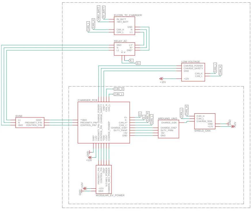
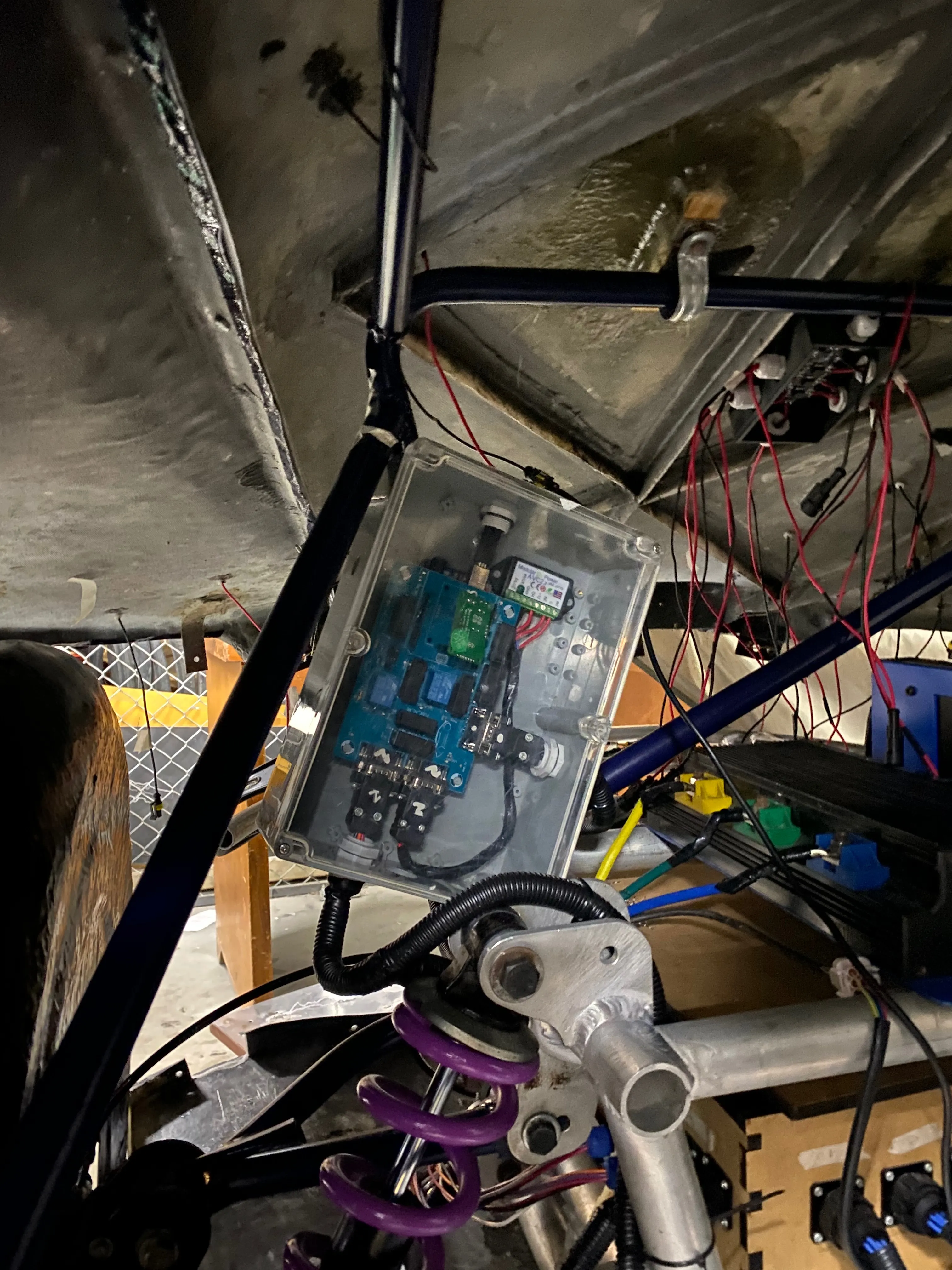
The charging system is split into two parallel subsystems that converge on the high voltage battery. The electronic side is a control PCB built around an Arduino UNO that interprets the J1772 control pilot signal, decides whether the EVSE is healthy and ready, and only then commands the BMS to close the charging contactor. A series of relays gate the charging signals, an optocoupler conditions the +/-12 V control pilot to a microcontroller-friendly level, and an MCP2515 transceiver gives the controller access to the car’s CAN bus so it can read the BMS and report state. An EVPower AVC2 module provides the impedance the J1772 standard requires the vehicle to present.
The mechanical side is a set of Aluminum 7075-T6 brackets that bolt the charger to the vehicle structure and survive frontal-impact loads. The two subsystems run in parallel rather than in series, so the bracket geometry and the PCB layout converge at the same milestone — useful because both have to fit the same physical envelope inside the cabin.
flowchart LR
    EVSE[J1772 EVSE] -- Control Pilot --> OPTO[Optocoupler]
    OPTO --> MCU[Arduino UNO FSM]
    AVC2[EVPower AVC2 Impedance] --> EVSE
    MCU -- CAN via MCP2515 --> BMS[Orion BMS]
    MCU -- enable --> RELAYS[Relay Bank]
    EVSE -- AC power --> RECT[Rectifier]
    RECT -- DC --> RELAYS
    RELAYS --> PACK[High-Voltage Battery Pack]
    BMS -- supervises --> PACK
How it works
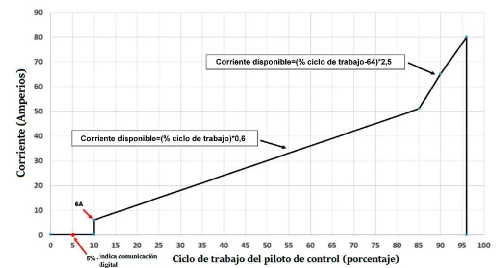
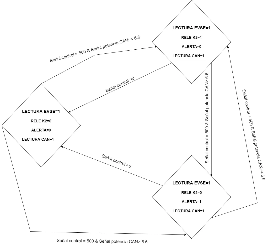
When the J1772 plug is inserted, the charger’s finite state machine moves through a defined sequence: it measures the duty cycle of the control pilot to learn the EVSE’s available current, checks that the cable is present and not faulted, verifies the requested charge does not exceed the network maximum, and only then signals the BMS to enable the main relay. If any check fails, the FSM blocks charging and surfaces an error. Each FSM transition is captured below.
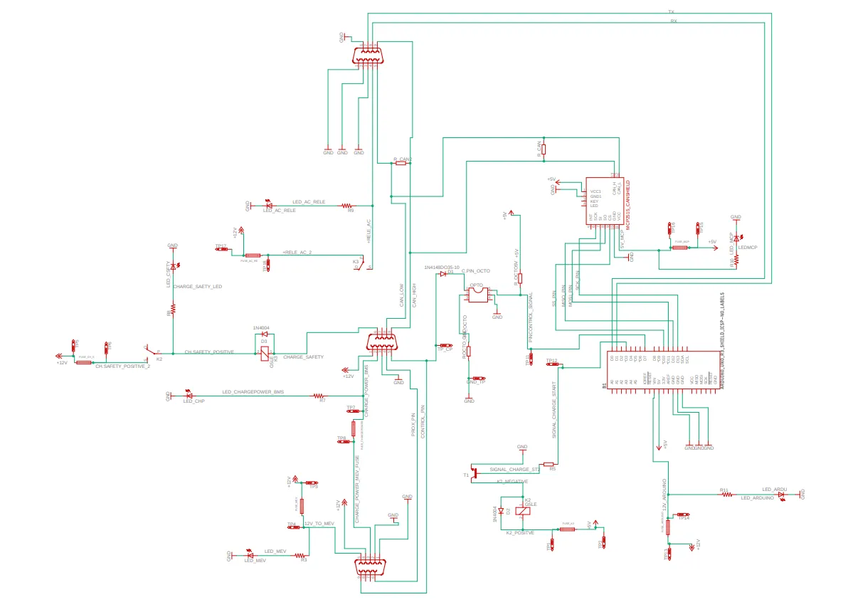
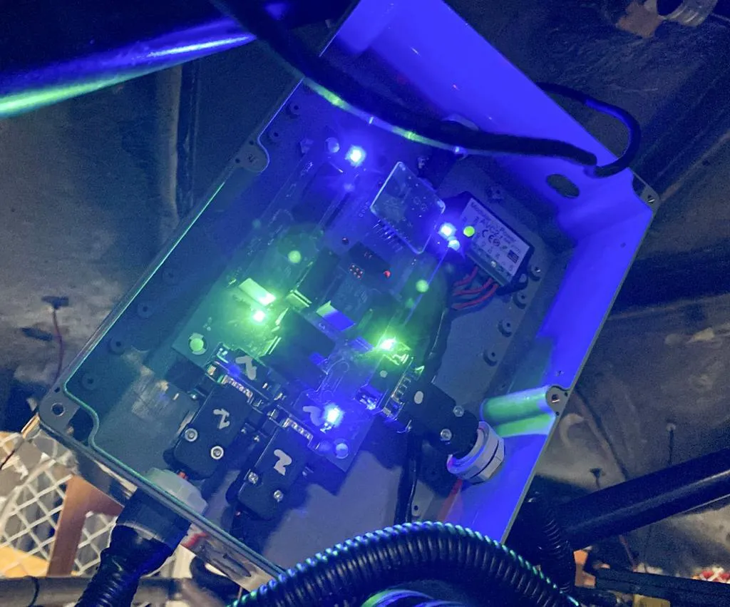
The control PCB is laid out around that FSM. A series of relays gate the charging-enable signal, overcurrent protections sit on each switched line, indicator LEDs surface power and signal-flow status to the technician, and the optocoupler isolates the +/-12 V control pilot from the microcontroller’s reading pin so that the standard’s signalling levels never reach the Arduino directly.
The mechanical side starts from material selection. The brackets were specified in Aluminum 7075-T6 sourced from the local supplier Asteco, chosen because it was both available in the Colombian supply chain and delivers the strength-to-weight ratio needed for an in-cabin restraint. The 7075-T6 datasheet quotes a yield strength of 520 MPa, but to allow for impurities or imperfections introduced during machining, the simulations were run with a yield reduced to 470 MPa as the working number — that is, “520 MPa nominal, reduced to 470 MPa due to manufacturing impurities” is the reference yield against which every safety factor reported below is computed.
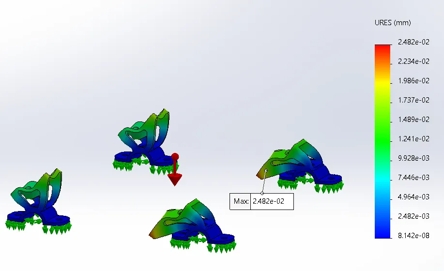
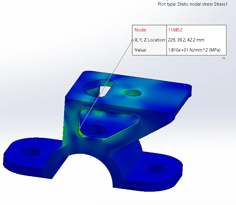
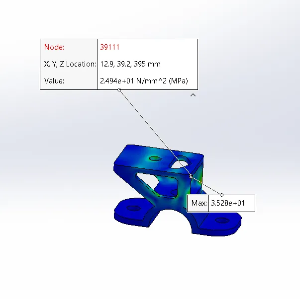
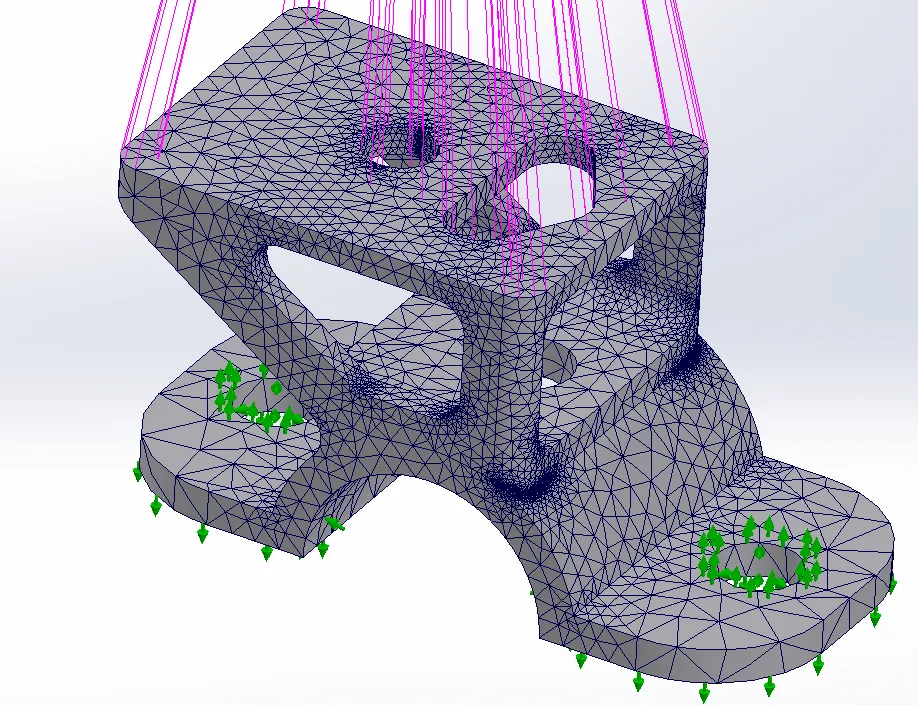
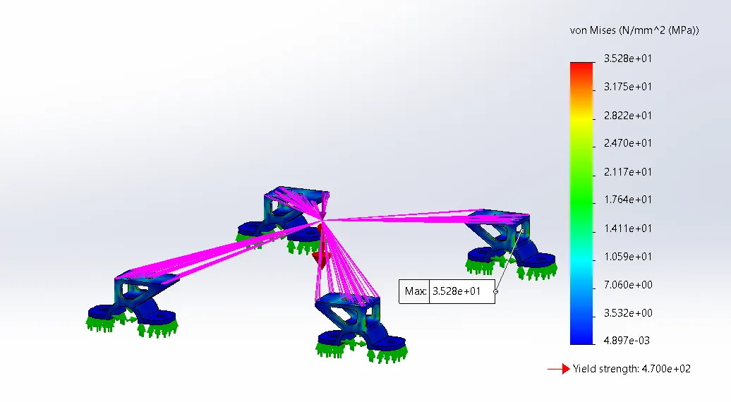
The static SolidWorks study applied a 5G frontal-impact load equivalent to 622 N at the charger’s centre of mass plus gravity (rectifier mass 12.7 kg → 124 N). The bracket returned a maximum Von Mises stress of 35.8 MPa and a safety factor of 13 against the working 470 MPa yield. The displacement field also stayed bounded — peak 0.024 mm under the worst case — and matched the deformation pattern that the team intuitively expected from a frontal impact.
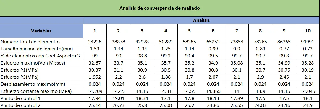
To validate that the FEA result was independent of the mesh, two sensors were placed on the assembly at the geometric features expected to drive the stress and displacement.
Then 10 simulations were run starting from a 34,238-element mesh (with 99 % of its elements at an aspect ratio below 3), each iteration reducing the minimum element size and increasing the element count, while logging the maximum Von Mises stress, maximum shear stress, maximum displacement and the values at both sensors. The sensor traces stayed flat across the iterations, the aspect-ratio quality stayed acceptable across all 10 runs, and the mesh was therefore declared converged.
To push precision further at the high-stress region, an adaptive H-method run was performed. The H-method confirmed a peak Von Mises stress of 35 MPa, in agreement with the static study and the converged mesh, which closed out the SolidWorks side of the validation.
As an external cross-check, the same assembly was re-run end-to-end in SimSolid against an equivalent 5G frontal-impact case. SimSolid uses a different solver than SolidWorks’ linear-elastic FEA, so a successful match between the two is independent evidence rather than a re-run of the same calculation.
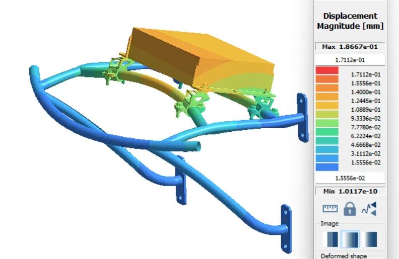
The SimSolid run produced a maximum displacement of 0.18 mm and a peak Von Mises stress of 42.7 MPa in the brackets — slightly higher than SolidWorks because the full-assembly contact behaviour adds load paths the static study could not see, but still an order of magnitude below the 470 MPa working yield. With both static studies in agreement, a modal analysis was run to identify the first natural frequency of the bracket assembly and to confirm the design is safe from resonance excitation in the vehicle.
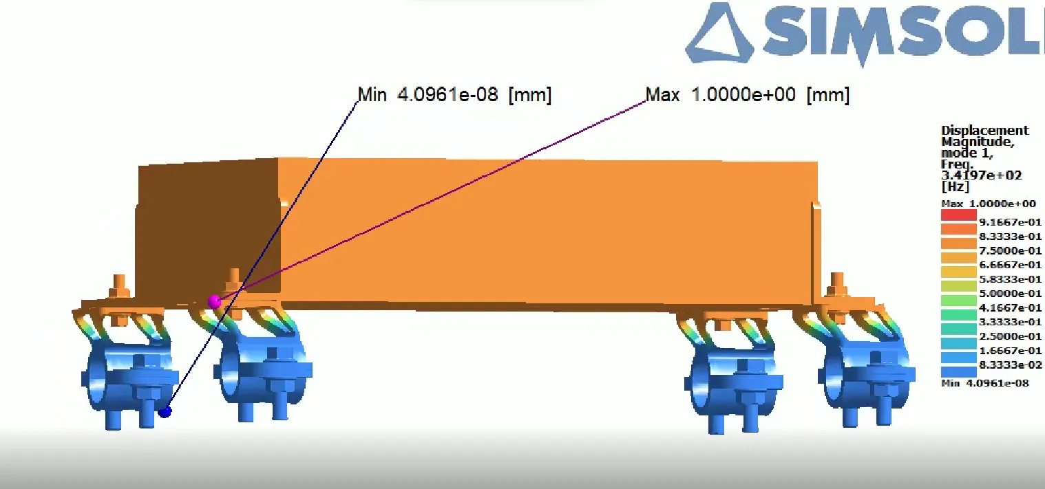
The result was a first natural frequency of 340 Hz. 340 Hz natural frequency = 20,400 RPM equivalent; no powertrain or rotating element on the KRATOS vehicle reaches that speed, so the bracket is safe from resonance. With the static, mesh-convergence, H-method, full-assembly impact and modal studies all in agreement, the bracket geometry was signed off for manufacturing.
Manufacturing happened at the EAFIT University machine shop, and the workshop access constraints were the binding tradeoff at this stage. The available CNC time on the university machine drove a simplification of the bracket geometry — the original revision included pocketing intended to shave further mass, but the time budget did not allow for the additional milling steps, so the team reverted to a slightly heavier geometry that fit the machining window without losing any of the validated safety margin. That tradeoff was much easier to swallow than it would have been on a tighter design, because the safety factor of 13 left ample headroom to spend on manufacturability.
What I learned
The biggest takeaway was that complying with a real automotive standard like J1772 forces every layer of the design to take protection seriously: the optocoupler, the impedance module, the relay sequencing and the FSM all exist because the standard refuses to let you cut corners. I also learned to treat finite element analysis as a chain of converging evidence rather than a single number — running a static study with conservative yield (Aluminum 7075-T6 from Asteco, 520 MPa nominal reduced to 470 MPa for impurities), a 10-iteration mesh convergence study, an adaptive H-method run, an independent SimSolid full-assembly impact analysis and a 340 Hz modal study on the same brackets gave us much higher confidence than any one of them alone. The modal study in particular caught a question that the static studies could not have asked, and the 20,400 RPM equivalent of the first natural frequency is the number that ultimately closed out resonance as a concern. Manufacturing constraints at the EAFIT University workshop also taught me to design the simplification path early: the final brackets had to drop their weight-reduction pockets to fit the machining time available, and that tradeoff was much easier to absorb because the geometry had been kept manufacturable from the first revision and because the 12.7 kg charger sat inside a safety factor of 13 that gave us room to spend.