Low-Voltage / High-Voltage PCB Integration — KRATOS Solar Car II.
Redesign of the KRATOS Solar Car II PCB stack, consolidating LV and HV distribution into fewer EAGLE-routed, OSHPARK-manufactured boards with better protection and connector standards.
- Year
- 2022
- Role
- Electronics Designer
- Domain
- Electrical
What it does
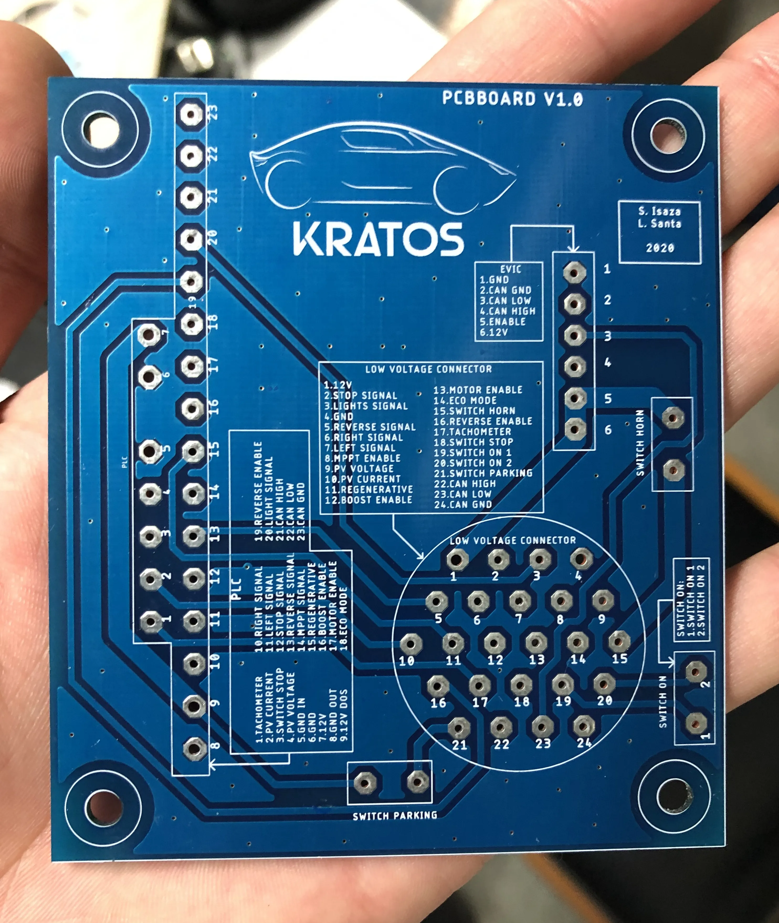
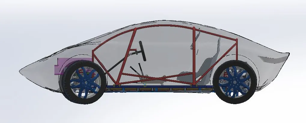
This project covers a ground-up redesign of the printed circuit boards used inside KRATOS Solar Car II. The previous season’s car had grown a sprawling set of small PCBs, each handling a narrow function, and the harness connecting them had become heavy and fragile. The new stack consolidates that fleet into a smaller number of boards that each cover a clearer slice of the vehicle: a low-voltage signal aggregator behind the dashboard, a high-voltage distribution board that works with the BMS, and a couple of new boards that unlock features the previous version could not support. The end result is fewer boards, fewer connectors, less mass and more reliable energy distribution, while still being maintainable in a workshop with limited equipment. As a side effect of the consolidation, the team also achieved a noticeable reduction in the total energy spent on the accessories side of the car, because the optimisation work that came with the redesign let several signal paths run with smaller protection components and shorter traces.
How it’s structured
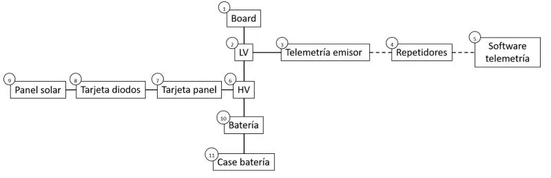
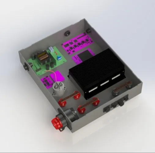
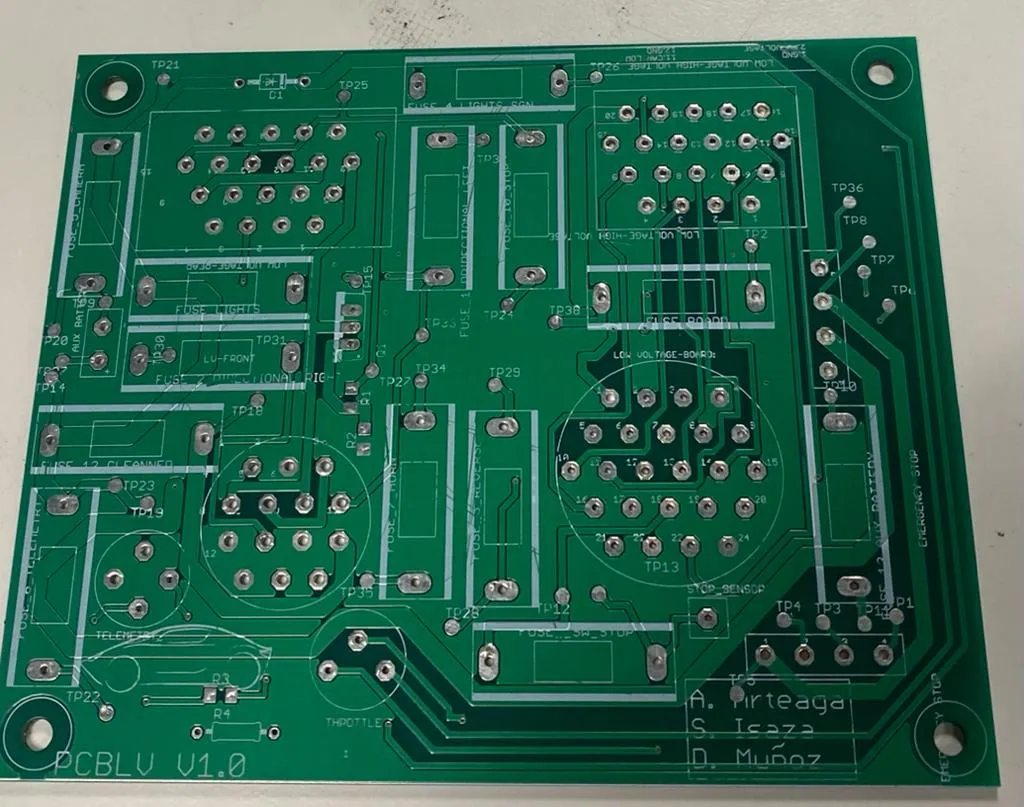
The redesign starts from a single block diagram of the vehicle that lists every unit that needs to exchange power or signals — drivers, BMS, dashboard, telemetry, charger, accessories — and the connections between them. From that diagram each PCB is given a clear scope: the low-voltage board collects sensor signals on their way to the dashboard and acts as a signal bus for high-power switching; the high-voltage board powers the motor drivers and works with the BMS to bring the battery online and offline; and a set of collection units wrap the boards together with the relays, busbar and BMS hardware so that the wiring harness lands in one place. Connectors are chosen at the architecture stage rather than at routing, because the failure mode the team most wanted to design out was accidental disconnection during the race. The same consideration drives the protection strategy: each board carries indicator LEDs and a defined set of fuses and protective elements, sized from the input/output characterisation, so that a technician can tell at a glance which board is healthy and which is the one to investigate.
How it works
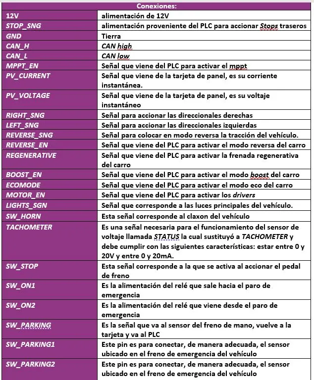
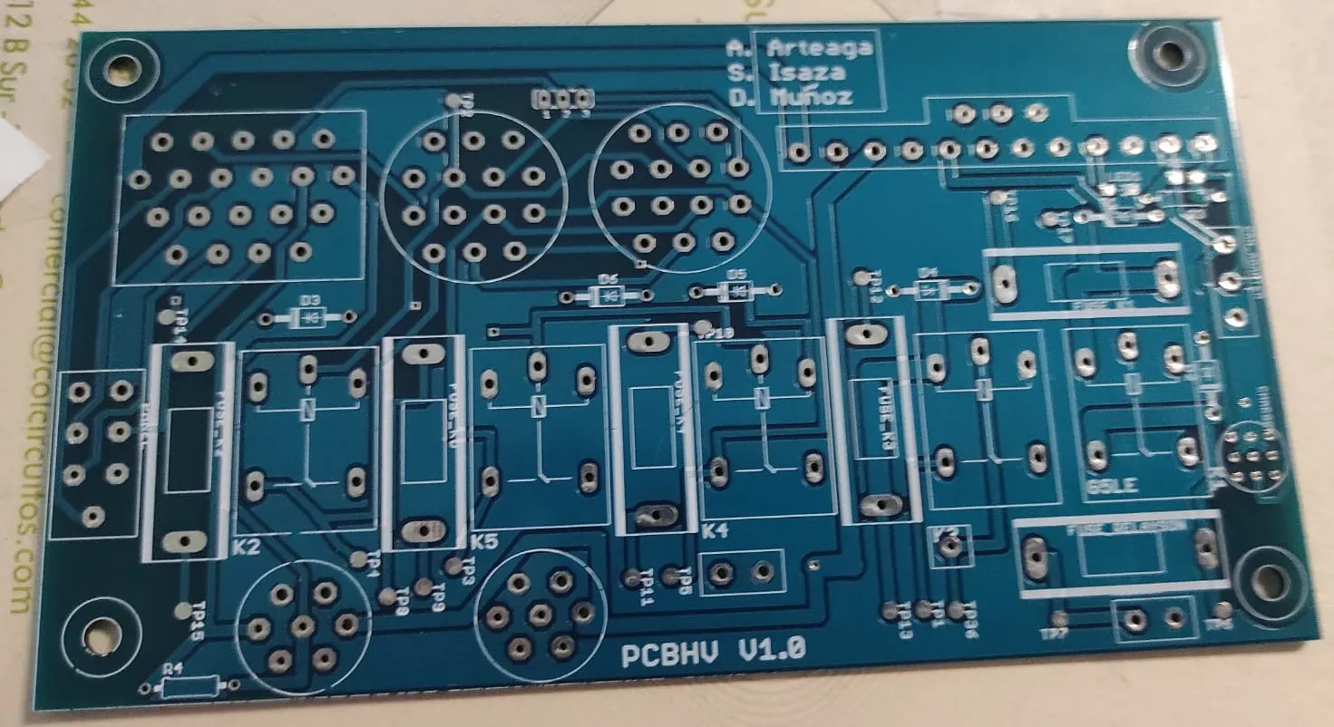
For each board the workflow runs the same way: characterise every input and output by voltage and current, derive the trace widths from those numbers, capture the schematic in EAGLE, route the layout while respecting the trace widths and the connector positions, and only then send the design out for manufacturing through OSHPARK as the manufacturing standard. The IO characterisation is captured in a single table that is the source of truth for trace widths, fuse ratings and connector pinouts — every downstream design choice references it.
With the table in hand, the schematic is captured in EAGLE for each board, with consistent symbol naming and net labels so that the layout step can pick up directly without re-tracing decisions. Once the schematic is signed off, the layout takes over and the trace widths derived from the IO table are placed against the connector positions chosen in the architecture stage.
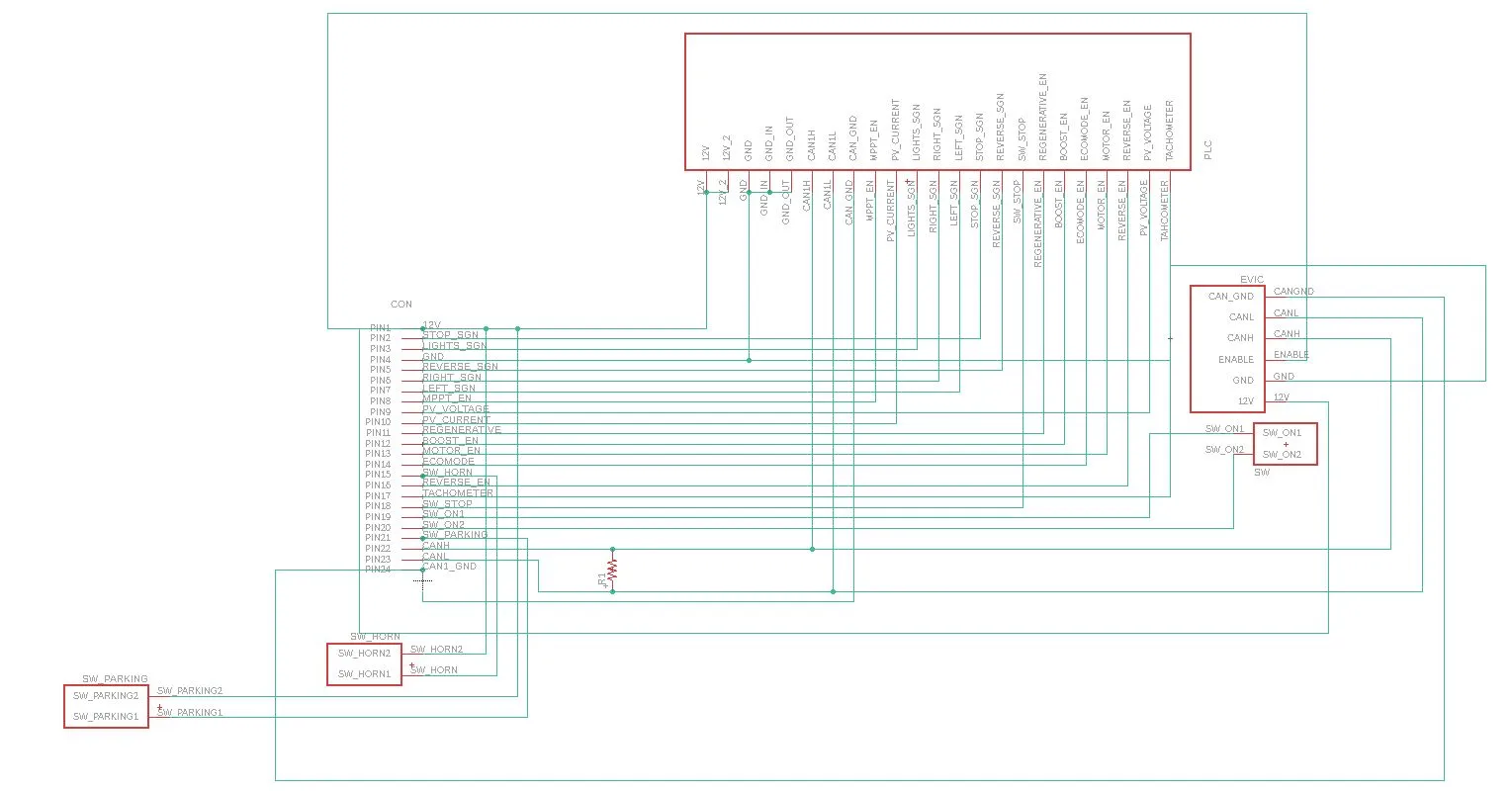
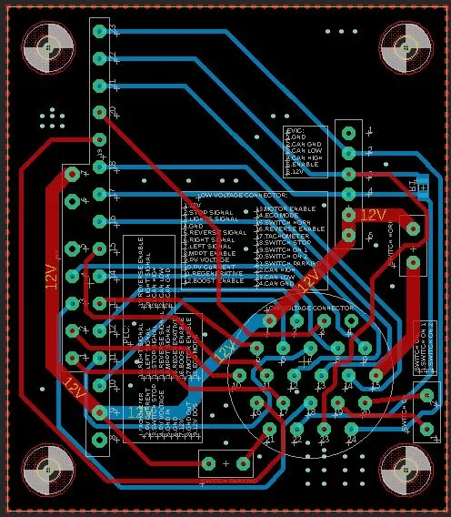
The low-voltage board pulls together all of the signals from across the vehicle and exposes them to the dashboard electronics; the high-voltage board hosts the contactors, switching, and protections that bring the pack online and feed the motor drivers; and shared protection components — fuses, TVS-style elements, indicator LEDs — are laid out consistently across the boards so a technician can find them quickly.
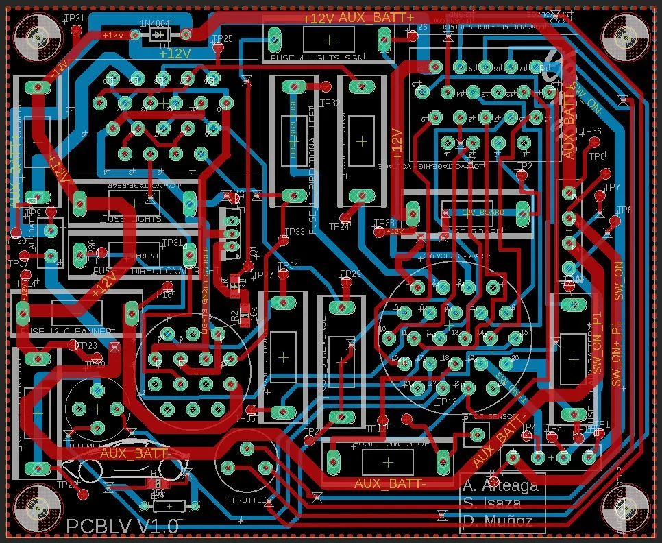
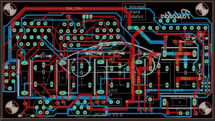
Once the bare boards arrive from OSHPARK, the assemblies are populated, fitted into the collection units, and integrated with the harnesses and BMS that arrive at the same housings.

What I learned
The biggest lesson was how much better the second-generation electronics became once we treated PCB consolidation as an architecture problem rather than a layout problem. Defining the block diagram and the IO characterisation table first — before opening EAGLE — made trace widths, connector choices and protection elements fall out naturally, and it kept the design honest about what each board needed to do. Choosing better connectors at the architecture stage paid off twice: it cut assembly time and it removed a class of race-day failure that the previous car was constantly fighting. Standardising on OSHPARK as the manufacturing partner also paid off — predictable lead times and consistent stack-ups meant that the layout-to-assembly handoff stopped being a source of surprises. I also learned how much the surrounding mechanical context shapes an electronics design: deciding where the collection units would live, and how the harness would land in them, drove the schematic just as much as the electrical requirements.
This electronics redesign was a team effort with Andrés Arteaga and David Muñoz, with Leonardo Santa Moreno mentoring the entire PCB design process from block diagram through to the OSHPARK orders.